The most flexible retro ROM replacement – open source hardware and software.
All posts by smarc
Disabling Firmware Write Protection | MrChromebox.tech
MrChromebox.tech website
Source: Disabling Firmware Write Protection | MrChromebox.tech
1. Synopsis — Jinja2 API
Source: 1. Synopsis — Jinja2 API
Graphics editor and image converter for Arduino, ESP32, Adafruit_GFX, u8g2, TFT_eSPI
UI graphics editor for embedded screens with pixel perfect code builder and export. Best for Arduino, STM32, ESP32. Converts images to uint32 and uint8 variables for Adafruit GFX, u8g2 and TFT_eSPI
Source: Graphics editor and image converter for Arduino, ESP32, Adafruit_GFX, u8g2, TFT_eSPI
Introduction_to_a_Self_Managed_Life
https://wiki.futo.org/index.php/Introduction_to_a_Self_Managed_Life:_a_13_hour_%26_28_minute_presentation_by_FUTO_software
Bally & Stern General Game ROM Chip & Jumper Info
| Bally & Stern General Game ROM Chip & Jumper Info The guide below is intended as a basic introduction to the process of changing ROM chips on the MPU board of your Bally or Stern pinball machine. It is designed to familliarize you with the terms of the parts and steps involved, and help you to get an idea of what may be required to replace or install new ROM chips on your board. Information in this article applies to Bally MPU board models AS-2518-17, AS-2518-35, AS-2518-133, and Stern MPU boards MPU-100, and MPU-200. See the following section on Determining What MPU Board You Have to determine which board your game has in it. This article contains the following sections:
Brief Overview of Changing ROM Chips:When changing ROM chips on your Bally or Stern MPU board, you will need to complete the following steps: 1. Determine what type of MPU board you have. Click here 2. Determine what type of chips you are installing. Click here 3. Determine whether or not your board is configured for the chips you are installing. Click here 4. Make any necessary changes to your board, for the types of chips you are installing. Each of these steps is described below. Determining What MPU Board You Have:Both Bally and Stern boards had their board ID number printed in the lower right corner of the MPU board, in white ink. Sometimes labels or stickers were put over the number, so you may need to remove a sticker or two to find the number. For Bally boards, you should find “AS-2518-17”, or “AS-2518-35”. On Stern boards, you should find “MPU-100” or “MPU-200”. The type of board your game has will determine what needs to be done to it in order to replace ROM chips. These boards were used in Bally and Stern games, respectively, from 1977 through 1984/1985. ROM chip locations on these boards are labeled U1, U2, U3, U4, U5, and U6. Note that not all boards use chips in all of these locations- most games only use two or three chips, but it can vary from game to game. Replacement ROM Chips:When installing new ROM chips on your Bally or Stern MPU board, you will need to determine what kind of chips you are installing. Once you know what kind of chips you are installing, you can then determine if your board is properly configured for those types of chips. If it isn’t, you can make some changes to the board so that it will work with the chips you are installing (described below). Most replacement ROM chips for Bally and Stern MPU boards are “EPROM” type chips. An EPROM chip is a chip that can be erased and reprogrammed. Many original (factory) ROM chips for Bally and Stern MPU boards are “PROM” type chips. A PROM chip is a chip that cannot be erased and reprogrammed. Some boards even came from the factory with a combination of EPROM and PROM chips installed. EPROM and PROM chips are not always interchangeable. You will need to determine what types of chips you are installing on your board. All chips should have some numbers printed on them which will help identify what kind of chips they are. Look for the following numbers on your chips:
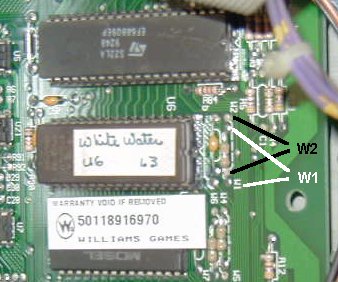
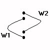
Once you have identified the types of chips you are installing, you can proceed to the next step, which is determining if your board is properly configured for the types of chips you are installing. Configuring Your MPU Board for New ROM Chips:Since several different types of ROM chips can be used on Bally and Stern MPU boards, the designers of these boards engineered a handy way of “configuring” or “setting up” the board for the types of chips being used. These boards use “jumpers”, which can be moved, or reconfigured, depending on the type of ROM chips being used. A jumper is basically just a piece of wire (often bare wire) which connects two points on the board. Changing a jumper basically means desoldering one end from one point, and connecting that end to another point. On Bally and Stern boards, the jumper points are labeled with the prefix “E”. For example, jumper #1 is labeled “E1”, and jumper #20 is labeled E20. Some jumpers also have “sub jumpers” that have an “A” prefix on them. For example, your board may have a jumper E16, and another jumper E16A. Here is a picture of two jumper locations on a late-model pinball MPU board- W1 and W2. (Late model boards use “W” for their prefix instead of “E”, and use what look like resistors instead of bare wire, for the jumpers):
Or, more clearly:
A jumper connection between either set of two points is considered “IN”, or “set”. A set of two points that doesn’t have a connection between them, is considered “OUT”, or “not set”. Jumpers will have to be set according to the type of ROM chips you are installing. This is where the process gets technical. To change jumper settings, you’ll need a soldering iron, some solder, de-soldering wick (or “braid”), or a de-soldering tool, and possibly a small piece of wire to use as a jumper. Use care when desoldering and soldering on these fragile circuit boards- too much heat from a soldering iron can lift solder pads and traces, and can damage the board. Excess solder can short the jumper to other connections nearby. Important Note: If you’re uncomfortable doing this kind of work, we strongly recommend leaving it to someone who is experienced. If you don’t have experience working electronic circuit boards, it can be too easy to make a mistake, or damage something beyond repair. It’s better to send the board out to have the work done, rather than risk damaging it yourself. Jumpers must be configured properly for the type of ROM chips being installed. If the board is not configured properly, then it will not work! Early Bally/Stern MPU Boards – Configuration Details:Bally AS-2518-17 and Stern MPU-100 boards will not only need jumper configuration, but will also need to have some physical modifications done to the board in order for it to use EPROM chips. These early boards were designed strictly for PROM chips only, so in order to use the newer style EPROM chips, they must be physically modified, or “altered” in order to work properly with EPROM chips. Bally games that used the early “-17” board were: Freedom, Evel Knievel, Night Rider, Eight Ball, Power Play, Mata Hari, Black Jack, and Strikes & Spares. Stern games that used the early “MPU-100” board were: Pinball, Stingray, Stars, Memory Lane, Lectronamo, Wild Fyre, Ted Nugent, Dracula, Trident, Hot Hand, Magic, and Cosmic Princess. Late Bally/Stern MPU Boards – Configuration Details:Bally AS-2518-35, AS-2518-133, and Stern MPU-200 boards will require only jumper changes to configure them for the particular type of ROM chip you are installing. No board modifications are necessary. The above information should be enough to familliarize you with what is required for installing new ROM chips on your particular MPU board. · If you are searching for replacement ROM chips, see our ROM Chips page.
|
OSINT Framework
Source: OSINT Framework
PCB Tracer: Reverse Engineering, Troubleshooting & Repair
Free browser-based Printed Circuit Board (PCB) reverse engineering tool for electronics. Trace signal paths through multi-layer PCBs with virtual X-Ray view. Annotate components, vias, traces, and pads. Perfect for PCB reverse engineering, circuit board reverse engineering, PCB analysis, PCB troubleshooting, PCB documentation, circuit board analysis, electronics troubleshooting, circuit board repair, PCB repair, and PCB learning. Features include: PCB trace, PCB tracing, printed circuit board trace, printed circuit board tracing, signal path tracing, via tracing, trace analysis, component annotation, PCB component identification, multi-layer PCB analysis, PCB x-ray view, X-Ray view, virtual X-Ray, PCB X-Ray, PCB annotation, PCB design, electronics reverse engineering, electronics tool, electronics learning, PCB viewer, PCB editor, online PCB tool, browser PCB tool, free PCB software, PCB reverse engineering software, PCB trace tool, PCB netlist, PCB schematic, KiCad export, BOM export, Bill of Materials, circuit connections, copper traces, SMD pads, through-hole pads, voltage buses, ground connections, board dimensions, PCB measurements, PCB scaling, debugging circuits, test points, component placement, pin connections, power nodes, ground nodes, PCB photographs, circuit documentation, PCB analysis tool, PCB reverse engineering tool, AI-powered component identification, artificial intelligence, Gemini, Claude, supervised learning, connection tracking, pin-to-pin connections, net building, net naming, assign meaningful names to nets, named nets, record measurements, identify components, generate BOM, generate netlist, generate schematic, KiCad schematic generation, two-point measurement, error checking, check for errors, explain circuit, troubleshoot circuit, circuit analysis, analyze circuit. No installation required.
Source: PCB Tracer: Reverse Engineering, Troubleshooting & Repair
Fusion Help | Parameters reference | Autodesk
Group Policy – Brave Help Center
Knowledge base for Brave Browser
Source: Group Policy – Brave Help Center