Nodemcu ESP8266 Pinout, Specs, Versions with detailed board layout
NodeMCU esp8266 wifi module is an open-source, low-cost, low-power MCU(microcontroller unit) development board. It has 17 GPIO pins(11 are Digital I/O pins), out of which one pin is an analog pin, 4 pins support PWM, 2 pairs are for UART(UART0 and UART1), and supports 1x SPI and 1x I2C protocol.
NodeMCU ESP8266 has 128Kb of RAM, 4 MB of Flash memory, and a maximum clock speed of 160MHz(80 -160). The operating current is 80mA(average).
The ESP8266 Integrates an 802.11b/g/n HT40 Wi-Fi transceiver chip for WiFi connectivity and gives it the additional advantage of creating its network thus allowing other devices to connect directly to it.
Note: When ESP8266 was released, its open-source firmware was called Nodemcu by the developers. But now the term “Nodemcu” usually refers to the ESP8266 Wifi module.
Table of Contents
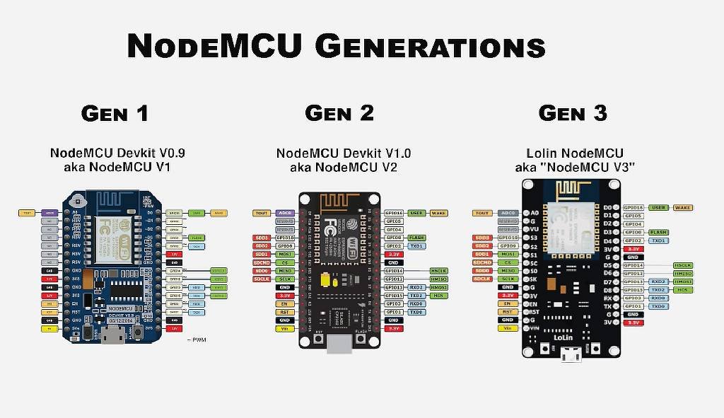
Nodemcu versions or generations:
As of now, there are three official versions of the Nodemcu: Nodemcu Devkit 0.9 or Nodemcu V1, Nodemcu Devkit 1.0 or Nodemcu V2, and Lolin Nodemcu or Nodemcu V3.
Nodemcu generations or versions
Nodemcu Esp8266 packaging style
Two main packaging types of Nodemcu are available in the market: Amica and LoLin.
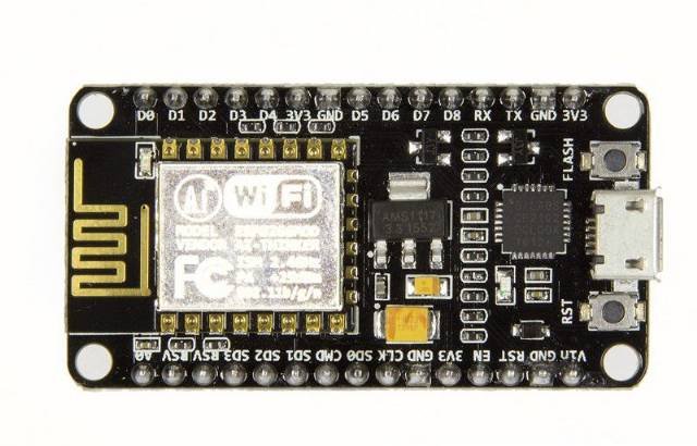
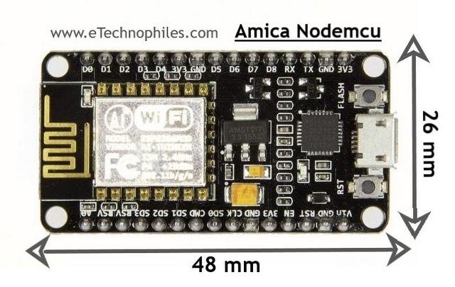
Amica Nodemcu package
The Amica Nodemcu has narrow pin spacing and measures 49mm x 26mm with a standard pin space of 0.1″ between pins and 0.9″ between rows.
Nodemcu esp8266 board in Amica package
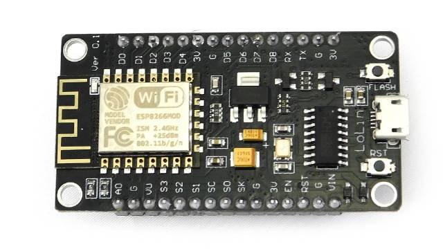
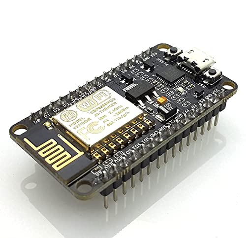
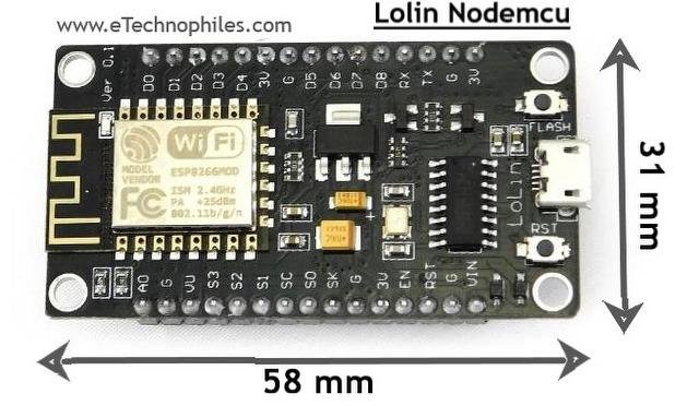
LoLin nodemcu package
The Lolin Nodemcu has a wider pin spacing and larger board layout than the Amica package. It measures 58mm x 32mm with a pin spacing of 0.1″ between pins and 1.1″ between rows.
LoLin Nodemcu ESP8266 Board
Note: The Amica NodeMCU is approximately 25% smaller in size than a closely compatible LoLin style NodeMCU.
Note: The LoLin board has 2 extra pins: VU and Ground pin. The VU pin is directly connected to the USB port power pin which can deliver 5V if the board is powered using a USB.
NodeMCU esp8266 wifi module is mostly used for IoT-based projects. By using NodeMCU ESP8266 Wifi Module, IoT applications become easier and cheaper.
Please note that the ESP8266 is a breadboard-friendly development board. And at its heart is a wifi module called ESP-12E. The ESP-12E is a tiny wifi module or the miniature version of ESP8266 that gives ESP8266 the functionality of Wireless communication. You can say, it is the brain of the ESP8266 Wifi module.
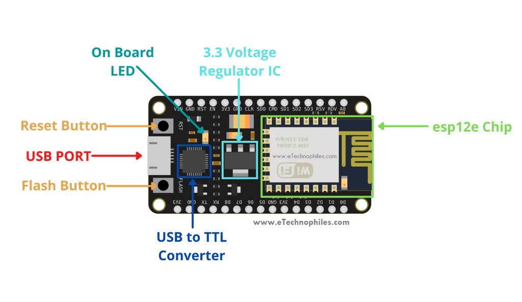
ESP8266 wifi module board layout
The Nodemcu wifi module comprises of ESP12E chip(the brain of the module), GPIO pins for easy interfacing, 3.3 Volt Voltage regulator, onboard LED, USB to serial converter IC, USB port, and more.
Nodemcu esp8266 board layout
ESP8266-12E wifi chip with antenna
This esp8266-12E or simply esp-12E chip is a member of the esp-xx series. There are 15 modules ranging from esp01 to esp15. These are mostly used for IoT applications due to their small form factor and low price.
Processor: The latest ESP12E board integrates a Tensilica LX106 32-bit RISC processor, which achieves extra-low power consumption and reaches a maximum clock speed of 160 MHz.
Uploading a program in ESP-12E using the micro USB cable is difficult as it requires a separate 3.3 voltage regulator, reset button, some resistors, and a USB to TTL converter IC.
But the development board Nodemcu ESP8266 module has everything mentioned above, thus it is easy to program it from your laptop/PC. Nodemcu ESP8266 has an Esp12e chip, a USB port to upload programs, and for power supply. It also has a reset and boot button.
Hence the Nodemcu is a better choice over the esp12e chip as it is easy to use, is breadboard-friendly, and comes at the same price.
Voltage regulator AMS1117
The esp12e chip works on 3.3 Volts. But since a micro USB cable provides 5 Volts, the Nodemcu has an on-board 3.3 V voltage regulator which is AMS1117.
USB to TTL/serial converter
To program the board using a USB cable, the USB to TTL/UART converter IC is needed. Nodemcu ESP8266 has CP2102 USB to UART bridge controller IC (in SMD QFN-28 package). Some old ESP8266 boards use CH340G USB to TTL converter IC (in SMD SOP-16 package).
Usually, the Lolin Nodemcu has CP2102 and Amica Nodemcu has CH340G USB to TTL converter IC.
Flash button
The boot or flash button is used while uploading the program. If you hold it down and press the EN/RST, the ES8266 will restart in flashing/uploading mode
Let’s have a look at the specifications of NodeMCU.
Microcontroller
ESP-8266 32-bit
NodeMCU Model
Amica(official)
Clock Speed
80-160 MHz
USB to Serial
CP2102
USB Connector
Micro USB
Operating Voltage
3.3V
Input Voltage
4.5V-10V
Flash Memory/SRAM
4 MB / 128 KB
GPIO Pins
17
Digital I/O Pins
11
Analog In Pins
1
PWM Pins
4
ADC Range
0-3.3V
UART/SPI/I2C
2 / 1 / 1
WiFi Built-In
802.11 b/g/n
Temperature Range
-40C – 125C
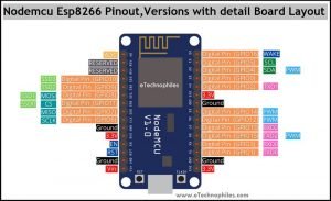
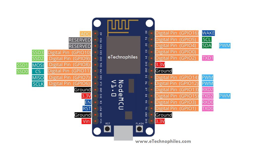
Nodemcu ESP8266 pinout
Nodemcu esp8266 pinout
As shown in the above image, there is a total of 17 GPIO(General Purpose Input Output) pins. Out of which only 11 pins are best to use. These 11 pins are mentioned in the table given below. We can use those pins as an input or output.
Pin Name
GPIO
Input
Output
D0
16
pull-up
pull-up
D1
5
OK
OK
D2
4
OK
OK
D3
0
pull-up
OK
D4
2
pull-up
OK
D5
14
OK
OK
D6
12
OK
OK
D7
13
OK
OK
D8
15
pull-down
OK
RX
3
pull-up
NO
TX
1
NO
pull-up
A0
ADC0
Analog
NO
Power pins
Vin: This pin can be used to power the esp8266 board. Up to 5V can be supplied to it. The Vin pin can be used to directly supply the Nodemcu esp8266 and its peripherals if you have a regulated 5V voltage source. This 5 volt is then converted to 3.3 volts using a voltage regulator as the esp12e chip requires 3.3V to operate.
Note: The Lolin ESP8266 module has one extra pin called VU. If the module is powered from a USB(5V), you can get 5V from the VU pin to power the external devices.
3.3 V: The board has three 3.3V pins. While the 3.3V pin is the output of a voltage regulator (CP2102), it can be used to power up the external components.
GND: There are a total of 4 such pins.
Note: All the GPIO pins of the ESP8266 are 3.3 V compatible(I/O) and are not 5V tolerant. Supplying 5 volts or more directly to any of the pins may damage the board.
ADC(Analog to digital) channel
ESP8266 has an inbuilt 10-bit ADC or analog-to-digital converter with only one ADC channel. In other words, the board has only one analog pin to read the analog voltage values from external devices like sensors and potentiometers.
This analog pin is marked as A0 on the board as given in the pinout diagram above.
The esp8266 board has 2 UART interfaces– RX0 and TX0 are UART0, RX2 and TX2 are UART1. The UART1 is used for uploading the firmware or program.
UART0 pins
U0 TXD (GPIO1)
U0 RXD (GPIO3)
UART1 pins
U1 TXD (GPIO15)
U1 RXD (GPIO13)
SPI pins
Unlike the three UART interfaces, the Esp8266 Nodemcu has only one set of SPI pins. The SPI protocol requires 4 pins: MOSI, MISO, SCLK, and CS.
GPIO 7: MISO
GPIO 8: MISO
GPIO 6: SCLK
GPIO 11: CS
I2C pins
The ESP8266 does not support any hardware I2C protocol, but it is possible to implement it in the programming part. So you may use any GPIO pins as I2C as long as you are aware of the I2C programming. Only two pins are required for I2C: SDA and SCLK.
Usually, the following GPIOs are used as I2C pins:
GPIO 4: SDA
GPIO 5: SCL
PWM pins
The board comes with 4 PWM-enabled pins. The PWM output can be used for driving digital motors and LEDs. PWM pins on the ESP8266 board are GPIO 4, GPIO 12, GPIO 14, and GPIO 15. OR digital pins D2, D5, D6, and D8.
EN or enable pin
EN stands for Enable, which enables the esp8266 chip i.e. ESP12E when pulled high. The chip works at minimum power when the EN pin is pulled low.
RST or reset Pin
This pin resets the board when pulled low. It works like the onboard reset button.
Wake pin(D0)
This pin is used to wake up the esp8266 chip from a deep sleep.
NOTE: EN, RST, and Wake pins are called the control pins of the ESP8266 board.
Nodemcu ESP8266 datasheet(ESP-12E):
To download the datasheet of this development board, click here.
Nodemcu dimensions
Amica nodemcu V2 dimensions:
The physical dimension of Amica or Nodemcu V2 is 4.8 X 2.6 in Centimeters.
Amica Nodemcu esp8266 dimensions
LoLin nodemcu V3 dimensions:
The physical dimension of LoLin or Nodemcu V3 is 5.8 X 3.1 Centimeters.
LoLin Nodemcu ESP8266 dimensions
FAQs
Why is ESP8266 used?
ESP8266 is used for its low-cost, integrated Wi-Fi capabilities, making it ideal for IoT projects and DIY electronics. Its small form factor, low power consumption, and ease of programming contribute to its popularity in applications like home automation, sensor networks, and remote monitoring.
Is NodeMCU and Arduino same?
No, NodeMCU and Arduino are not the same. NodeMCU is a development board based on the ESP8266 microcontroller, primarily used for IoT projects and Wi-Fi connectivity. Arduino is a popular open-source electronics platform based on various microcontrollers, offering a wide range of development boards for different applications.
What language is used for NodeMCU?
NodeMCU primarily uses Lua for programming, but C/C++ (via Arduino IDE) and MicroPython are also options.
Milk-V Duo is an ultra-compact embedded development platform based on the CV1800B chip. It can run Linux and RTOS, providing a reliable, low-cost, and high-performance platform for professionals, industrial ODMs, AIoT enthusiasts, DIY hobbyists, and creators.
The Milk-V Duo 256M is an upgraded version of Duo with a memory boost to 256M, catering to applications demanding larger memory capacities. It features the SG2002 computing series chip, elevating computational power to 1.0TOPS@INT8. It enables seamless switching between RISC-V/ARM architectures and supports simultaneous operation of dual systems. Additionally, it includes an array of rich GPIO interfaces such as SPI, UART, suitable for a wide range of hardware development in edge intelligent monitoring, including IP cameras, smart peephole locks, visual doorbells, and more.
ESP8266, in it’s default configuration, boots up into the serial modem mode. In this mode you can communicate with it using a set of AT commands. AT commands that ESP8266 supports, explain what they do and how to use them.
Historically AT commands are based on the Hayes Command Set and these are no different.
ESP8266 expects <CR><LF> or CarriageReturn and LineFeed at the end of each command, but just<CR> seems to work too.
Command variants
Each command can have up to 4 variants changing the function of it. You can chose between them by appending one of four possible values to the end of the root command itself. These four appendices can have the following values "",=<parameter|[parameters]>,"?",=?
Type
Example
Description
Test
AT+CIPSTART=?
Query the range of values (So far only AT+CWMODE=? uses it)
Query
AT+CMD?
Returns the current value of the parameter.
Set
AT+CMD=Parameter
Set the value of user-defined parameters in commands and run.
Execute
AT+CMD
Runs commands with no user-defined parameters.
Note:
Not all AT commands support all 4 variants.
[] = default value, not required or may not appear.
String values require double quotation marks, for example: AT+CWSAP="ESP756190","21030826",1,4.
Enable echo (Sends back received command before response)
Note:
I haven’t had any luck with this command yet. Both ATE0 and ATE1 return no this fun. ATE returns OK
This changed with ESP-12 where the command functions exactly as expected!
mode: An integer designating the mode of operation either 1, 2, or 3. 1 = Station mode (client) 2 = AP mode (host) 3 = AP + Station mode (Yes, ESP8266 has a dual mode!)
Notes:
ESP-12 came configured as host with ssid set to ESP_A0A3F2, no password, channel 1 You can use AT+CWSAP? to find the current settings.
On ESP-01 I have had no luck with the set version of this command (AT+CWLAP=...). If you know what it does please let me know.
On ESP-12, the Set version of the command allows to see if a certain SSID, with certain MAC on certain channel exists. If it doesit is returned as one line of the Execute version of this command.
STATUS:status +CIPSTATUS:id,type,addr,port,tetype OK
Get information about connection.
Parameters:
status:
2: Got IP
3: Connected
4: Disconnected
id: id of the connection (0~4), for multi-connect
type: String, “TCP” or “UDP”
addr: String, IP address.
port: port number
tetype:
0 = ESP8266 runs as a client
1 = ESP8266 runs as a server
Note:
On ESP-01 this command returns STATUS:1 instead (no extra info, but status changes) On 0018000902-AI03 this command returns STATUS:2 instead (no extra info, but status changes)
Set length of the data that will be sent. For normal send (single connection).
Set
AT+CIPSEND=id,length
SEND OK
Set length of the data that will be sent. For normal send (multiple connection).
Execute
AT+CIPSEND
Send data. For unvarnished transmission mode.
Normal Mode
Parameters:
id: ID no. of transmit connection
length: data length, MAX 2048 bytes
Unvarnished Transmission Mode
Wrap return “>” after execute command. Enters unvarnished transmission, 20ms interval between each packet, maximum 2048 bytes per packet. When single packet containing “+++” is received, it returns to command mode.