Source: How to fix an unresponsive Unifi Cloud Key | David Mello
Category Archives: Hardware
New Raspberry Pi Zero 2 Upgrades To Quad-Core Processor
OctoWS2811 LED Library, Driving Hundreds to Thousands of WS2811 LEDs with Teensy 3.0
mensikv/VMs-macro-keyboard: Macro keyboard with 8x cherry mx and a rotary encoder using Arduino Micro
Zynqberry, a Xilinx Zynq FPGA Board with Raspberry Pi 2/3 Form Factor
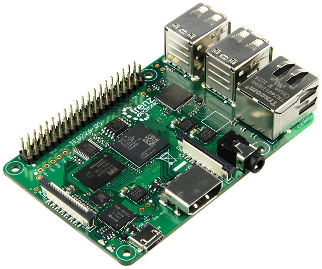
Earlier this year, I wrote about Trenz Electronic’s Xilinx Zynq Ultrascale+ system-on-module, but I’ve just found out I missed another interesting product
Source: Meet Zynqberry, a Xilinx Zynq FPGA Board with Raspberry Pi 2/3 Form Factor – CNX Software
How to Unlock SPA2102
To reset the SPA-2102 to factory defaults follow these steps:
Plug in power adapter.
Plug in a phone to ‘Phone 1′ port of the SPA-2102.
Dial **** You should hear ‘Configuration Option Menu’.
Dial 73738# (RESET#) Press 1 to confirm the reset.
The SPA-2102 should now have been reset to factory default settings.
You may need to do the following to set up web management depending on which interface you are coming in on:
Dial **** into the phone connected to the ATA device. You should hear ‘Configuration Option Menu’.
Dial 7932 then press 1 to enable. Hang up when you hear option saved.
2. Get access to your SPA-2102 web interface. Plug in Ethernet cable to router and wait for several seconds.
Dial ****110# Listen to IP Address which is read back to you.
Plug your PC into the LAN (Ethernet) port of the SPA-2102. Enter IP Address into your web browser (For example. http://192.168.1.10). You should now see the Linksys SPA-2102 Web Interface
nccgroup/TPMGenie: TPM Genie is an I2C bus interposer for discrete Trusted Platform Modules
Hacking the newer APC ups’s – mini worklog/howto | OCAU Forums
Update PowerEdge Servers with Platform Specific Bootable ISO | Dell US
How to Debounce switches on the Arduino?
POSSIBLE SOLUTIONS
There are many ways to work around this problem, here are 2 simple ones, with their pros and cons:
-
Using a simple “delay()” function.
-
Using the “millis” function.
Using a simple “Delay()” Function
The way this works is when you start pressing the switch the first time the Arduino detects the desired state (LOW in this case) the delay() is started and waits between 50 and 200 milliseconds, this pauses the entire code on the Arduino until the delay is expired.
The reasoning is that the delay will be long enough to not let the Arduino read the bouncing and only register one switch press.
This method works fairly well but there are pros and cons:
Cons:
-
The delay() function is a ‘blocking’ function, freezing the execution of the Arduino code, so that when the delay is started nothing else can be done, such as reading a sensor or displaying values on an LCD, until the delay is expired.
-
It can’t be used inside Interrupts.
Pros:
-
Requires less coding than the millis() function and doesn’t need variables.
-
Easy to use and adequate for simple projects.
Using the “millis()” Function
The millis() function, when called, returns a time value (in milliseconds) that represent the time passed since the Arduino was powered up.
This timer is started automatically at power up without the need of any coding, so you can just call the function “millis()” to get the current value.
So by using some variables we can know the amount of time passed and use this instead of the delay() function.
The big advantage is that the millis() function is also a “non-blocking function” which means that the Arduino is not paused or frozen, so you can do other things unlike the delay() function which pauses the code completely.
Pros and cons:
Cons:
-
The millis() function requires a bit more coding since it requires variables compare to know how much time as passed.
-
The millis() timer will overflow (reset to zero) after approximately 49 days, no really a problem in most cases but something to keep in mind depending on how you use it.
Pros:
-
Since it doesn’t block or stops the code, you can do other things like check sensors or update display.
-
Can be used inside interrupts unlike the delay() function.
-
Useful for accurate timing of actions inside projects.
CONNECTIONS
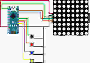

In this tutorial we will be connecting 4 tact switches.
The black one will demonstrate switch bouncing.
The red and blue will show the delay() and millis() functions.
The yellow one will reset the LED Matrix counter.
THE CODE
All the switches are using the Arduino INPUT_PULLUP resistors to set their un-pressed state to HIGH.
We are also using some button state variables to make sure that when a switch is pressed and held down, the counter does not keep increasing.
Both the delay() and millis() function have a value of 100ms for debounce.
As always please watch the tutorial video for more information.
/* Arduino Switch Debounce Examples

Created by Yvan / https://Brainy-Bits.com

This code is in the public domain...

You can: copy it, use it, modify it, share it or just plain ignore it!
Thx!

*/

// Needed for the LED Matrix
#include <MD_Parola.h>
#include <MD_MAX72xx.h>
#include <SPI.h>

#define HARDWARE_TYPE MD_MAX72XX::ICSTATION_HW
/*  PAROLA_HW,    ///< Use the Parola style hardware modules.
    GENERIC_HW,   ///< Use 'generic' style hardware modules commonly available.
    ICSTATION_HW, ///< Use ICStation style hardware module.
    FC16_HW       ///< Use FC-16 style hardware module.
*/

//Pins from the LED Matrix to the Arduino
#define MAX_DEVICES 1
#define CLK_PIN   13
#define DATA_PIN  11
#define CS_PIN    10

//Switches pins connected to Arduino
#define switchpinBlack 6
#define switchpinRed 5
#define switchpinBlue 4
#define switchpinYellow 3

// Variable used for millis debounce
long TimeOfLastDebounce = 0;  // holds the last time the switch was pressed
long DelayofDebounce = 100;  // amount of time that needs to be experied between presses

// Variable used to save the state of the switches
// Needed so the counter only goes +1 for each keypress

int BlackButtonState = 0;
int RedButtonState = 0;
int BlueButtonState = 0;

// Variable to hold the value of the counter
int displaycounter=0;

// Hardware SPI connection
MD_Parola P = MD_Parola(HARDWARE_TYPE, CS_PIN, MAX_DEVICES);


void setup(void)
{
  P.begin();
  P.setTextAlignment(PA_CENTER);

//All switches use the Arduino input pullup resistors
  pinMode(switchpinBlack, INPUT_PULLUP);
  pinMode(switchpinRed, INPUT_PULLUP);
  pinMode(switchpinYellow, INPUT_PULLUP);
  pinMode(switchpinBlue, INPUT_PULLUP);
}

void loop(void)
{
    // Black Switch - No Debounce
    if (digitalRead(switchpinBlack) == LOW && BlackButtonState == 0) {
      BlackButtonState=1;
      displaycounter++;
      P.print(displaycounter);
    } else {
      if (BlackButtonState == 1 && digitalRead(switchpinBlack) == HIGH) {
        BlackButtonState=0;
      }
    }


    // Red Switch - Debounce using a delay() command
    if (digitalRead(switchpinRed) == LOW && RedButtonState == 0) {
      delay(100);  // The higher the Delay the less chance of bouncing
      RedButtonState=1;
      displaycounter++;
      P.print(displaycounter);
    } else {
      if (RedButtonState == 1 && digitalRead(switchpinRed) == HIGH) {
        RedButtonState=0;
      }
    }


    // Blue Switch - Debounce using a 'millis' timer
    if (digitalRead(switchpinBlue) == LOW && BlueButtonState == 0) {

      // check if enough time has passed to consider it a switch press
      if ((millis() - TimeOfLastDebounce) > DelayofDebounce) {
        BlueButtonState=1;
        displaycounter++;
        TimeOfLastDebounce = millis();
        P.print(displaycounter);
      }
    } else {
      if (BlueButtonState == 1 && digitalRead(switchpinBlue) == HIGH){
        BlueButtonState=0;
      }
    }

    // Yellow Switch - Reset Counter
    if (digitalRead(switchpinYellow) == LOW) {
      displaycounter=0;
    }
  }