Category Archives: arduino
Home · espressif/ESP8266_AT Wiki
Source: Home · espressif/ESP8266_AT Wiki
ESP8266 – AT Command Reference · room-15
ESP8266 – AT Command Reference
ESP8266, in it’s default configuration, boots up into the serial modem mode. In this mode you can communicate with it using a set of AT commands. AT commands that ESP8266 supports, explain what they do and how to use them.
Historically AT commands are based on the Hayes Command Set and these are no different.
AT Commands
Index of all known AT commands
Line termination
ESP8266 expects <CR><LF> or CarriageReturn and LineFeed at the end of each command, but just<CR> seems to work too.
Command variants
Each command can have up to 4 variants changing the function of it. You can chose between them by appending one of four possible values to the end of the root command itself. These four appendices can have the following values "",=<parameter|[parameters]>,"?",=?
| Type | Example | Description |
|---|---|---|
| Test | AT+CIPSTART=? | Query the range of values (So far only AT+CWMODE=? uses it) |
| Query | AT+CMD? | Returns the current value of the parameter. |
| Set | AT+CMD=Parameter | Set the value of user-defined parameters in commands and run. |
| Execute | AT+CMD | Runs commands with no user-defined parameters. |
Note:
- Not all AT commands support all 4 variants.
- [] = default value, not required or may not appear.
- String values require double quotation marks, for example:
AT+CWSAP="ESP756190","21030826",1,4. - Baud rate = 115200
- AT instruction ends with “\r\n”
Commands
AT – Test AT startup
| Variant | Command | Response | Function |
|---|---|---|---|
| Execute | AT | OK | Test if AT system works correctly |
AT+RST – Restart module
| Variant | Command | Response | Function |
|---|---|---|---|
| Execute | AT+RST | OK | Reset the module |
ESP-01 Output after reset:
 ets Jan  8 2013,rst cause:4, boot mode:(3,7)

wdt reset
load 0x40100000, len 24444, room 16
tail 12
chksum 0xe0
ho 0 tail 12 room 4
load 0x3ffe8000, len 3168, room 12
tail 4
chksum 0x93
load 0x3ffe8c60, len 4956, room 4
tail 8
chksum 0xbd
csum 0xbd

ready
ESP-12 Output after reset:
\0x04B1\0x85 \0xff\0x13:'\0xe0;\0xcc;!G\0xfa\0x11\0xa9R\0xc6\0x83\0x01\0xd9\0x81
[Vendor:www.ai-thinker.com Version:0.9.2.4]

ready
AT+GMR – View version info
| Variant | Command | Response | Function |
|---|---|---|---|
| Execute | AT+GMR | version, OK |
Print firmware version |
Parameters:
version: firmware version number
ESP-01 output:
00160901
ESP-12 output:
0018000902-AI03
AT+GSLP – Enter deep-sleep mode
| Variant | Command | Response | Function |
|---|---|---|---|
| set | AT+GSLP=time |
time OK |
Enter deep sleep mode for time milliseconds |
parameters:
time: Time to sleep in milliseconds
Example:
AT+GSLP=1500
Note:
Hardware has to support deep-sleep wake up (Reset pin has to be High).
ATE – Enable / Disable echo
| Variant | Command | Response | Function |
|---|---|---|---|
| Execute | ATE0 | OK | Disable echo (Doesn’t send back received command) |
| Execute | ATE1 | OK | Enable echo (Sends back received command before response) |
Note:
I haven’t had any luck with this command yet. Both ATE0 and ATE1 return no this fun.
ATE returns OK
This changed with ESP-12 where the command functions exactly as expected!
AT+CWMODE – WIFI mode(station, AP, station + AP)
| Variant | Command | Response | Function |
|---|---|---|---|
| Test | AT+CWMODE=? | +CWMODE:(1-3) OK | List valid modes |
| Query | AT+CWMODE? | +CWMODE:mode OK |
Query AP’s info which is connect by ESP8266. |
| Execute | AT+CWMODE=mode |
OK | Set AP’s info which will be connect by ESP8266. |
Parameters:
mode: An integer designating the mode of operation either 1, 2, or 3.
1 = Station mode (client)
2 = AP mode (host)
3 = AP + Station mode (Yes, ESP8266 has a dual mode!)
Notes:
ESP-12 came configured as host with ssid set to ESP_A0A3F2, no password, channel 1 You can use AT+CWSAP? to find the current settings.
AT+CWJAP – Connect to AP
| Variant | Command | Response | Function |
|---|---|---|---|
| Query | AT+CWJAP? | + CWJAP:ssid OK |
Prints the SSID of Access Point ESP8266 is connected to. |
| Execute | AT+CWJAP=ssid,pwd |
OK | Commands ESP8266 to connect a SSID with supplied password. |
Parameters:
ssid:String, AP’s SSIDpwd:String, not longer than 64 characters
Example:
AT+CWJAP="my-test-wifi","1234test"
Example AT+CWJAP?:
+CWJAP:"my-test-wifi"
AT+CWLAP – Lists available APs
| Variant | Command | Response | Function |
|---|---|---|---|
| Set | AT+CWLAP=ssid,mac,ch |
+CWLAP:ecn,ssid,rssi,mac OK |
Search available APs with specific conditions. |
| Execute | AT+CWLAP | AT+CWLAP:ecn,ssid,rssi,mac OK |
Lists available Access Points. |
Parameters:
ecn:- 0 = OPEN
- 1 = WEP
- 2 = WPA_PSK
- 3 = WPA2_PSK
- 4 = WPA_WPA2_PSK
ssid: String, SSID of APrssi: signal strengthmac: String, MAC address
Note:
On ESP-01 I have had no luck with the set version of this command (AT+CWLAP=...). If you know what it does please let me know.
On ESP-12, the Set version of the command allows to see if a certain SSID, with certain MAC on certain channel exists. If it doesit is returned as one line of the Execute version of this command.
Example AT+CWLAP:
+CWLAP:(3,"CVBJB",-71,"f8:e4:fb:5b:a9:5a",1)
+CWLAP:(3,"HT_00d02d638ac3",-90,"04:f0:21:0f:1f:61",1)
+CWLAP:(3,"CLDRM",-69,"22:c9:d0:1a:f6:54",1)
+CWLAP:(2,"AllSaints",-88,"c4:01:7c:3b:08:48",1)
+CWLAP:(0,"AllSaints-Guest",-83,"c4:01:7c:7b:08:48",1)
+CWLAP:(0,"AllSaints-Guest",-83,"c4:01:7c:7b:05:08",6)
+CWLAP:(4,"C7FU24",-27,"e8:94:f6:90:f9:d7",6)
+CWLAP:(2,"AllSaints",-82,"c4:01:7c:3b:05:08",6)
+CWLAP:(3,"QGJTL",-87,"f8:e4:fb:b5:6b:b4",6)
+CWLAP:(4,"50EFA8",-78,"74:44:01:50:ef:a7",6)
+CWLAP:(0,"optimumwifi",-78,"76:44:01:50:ef:a8",6)
+CWLAP:(3,"BHQH4",-95,"18:1b:eb:1a:af:5b",6)
+CWLAP:(3,"NETGEAR49",-86,"84:1b:5e:e0:28:03",7)
+CWLAP:(3,"ngHub_319332NW00047",-56,"20:e5:2a:79:b1:2f",11)
+CWLAP:(3,"BFZR4",-73,"18:1b:eb:1d:c3:91",11)
+CWLAP:(1,"5FFVL",-82,"00:26:b8:b5:c0:f2",11)
+CWLAP:(3,"59G6D",-77,"00:7f:28:6d:91:7b",11)
+CWLAP:(3,"N16FU",-53,"20:cf:30:ce:60:fe",11)
+CWLAP:(3,"ITS",-82,"90:72:40:21:5f:76",11)
+CWLAP:(3,"ITS",-79,"24:a2:e1:f0:04:e4",11)
Example AT+CWLAP="N16FU","20:cf:30:ce:60:fe",11:
+CWLAP:(3,"N16FU",-53,"20:cf:30:ce:60:fe",11)
AT+CWQAP – Disconnect from AP
| Variant | Command | Response | Function |
|---|---|---|---|
| Execute | AT+CWQAP | OK | Disconnect ESP8266 from the AP is currently connected to. |
Note:
After running this command, if you run AT+CWJAP? it still shows the AP you were connected to before. Back to Index
AT+CWSAP – Configuration of softAP mode
| Variant | Command | Response | Function |
|---|---|---|---|
| Query | AT+CWSAP? | +CWSAP:ssid,pwd,ch,ecn OK |
Query configuration of ESP8266 softAP mode. |
| Set | AT+CWSAP=ssid,pwd,ch,ecn |
OK | Set configuration of softAP mode. |
Parameters:
ssid: String, ESP8266’s softAP SSIDpwd: String, Password, no longer than 64 charactersch: channel idecn:- 0 = OPEN
- 2 = WPA_PSK
- 3 = WPA2_PSK
- 4 = WPA_WPA2_PSK
Example
AT+CWSAP="esp_123","1234test",5,3
AT+CWSAP? => +CWSAP:"esp_123","1234test",5,3
AT+CWLIF – List clients connected to ESP8266 softAP
| Variant | Command | Response | Function |
|---|---|---|---|
| Execute | AT+CWLIF | [ip,other] OK |
List information on of connected clients. |
Parameters:
ip: IP address of a client connected to the ESP8266 softAP other: Other info, look at example. I don’t know what it means yet.
Example (ESP-01):
AT+CWLIF

192.168.4.100,3fff50b4:3fff50ba:3fff50c0:3fff50c6:3fff50cc:3fff50d2

OK
Example (ESP-12):
AT+CWLIF

192.168.4.100,c0:ee:fb:25:33:ec

OK
I ran the command after connecting to the ESP8266 with my cellphone.
AT+CWDHCP – Enable/Disable DHCP
| Variant | Command | Response | Function |
|---|---|---|---|
| Set | AT+CWDHCP=mode,en |
OK | Enable or disable DHCP for selected mode |
Parameters:
mode:- 0 : set ESP8266 as a softAP
- 1 : set ESP8266 as a station
- 2 : set both ESP8266 to both softAP and a station
en:- 0 : Enable DHCP
- 1 : Disable DHCP
Note:
This command doesn’t seem to work on firmware 00160901 (ESP-01) nor 0018000902-AI03 (ESP-12).
AT+CIPSTAMAC – Set MAC address of ESP8266 station
| Variant | Command | Response | Function |
|---|---|---|---|
| Query | AT+CIPSTAMAC? | +CIPSTAMAC:mac OK |
Print current MAC ESP8266’s address. |
| Execute | AT+CIPSTAMAC=mac |
OK | Set ESP8266’s MAC address. |
Parameters:
mac: String, MAC address of the ESP8266 station.
Example:
AT+CIPSTAMAC="18:aa:35:97:d4:7b"
Note:
This command doesn’t seem to work on firmware 00160901
AT+CIPAPMAC – Set MAC address of ESP8266 softAP
| Variant | Command | Response | Function |
|---|---|---|---|
| Query | AT+CIPAPMAC? | +CIPAPMAC:mac OK |
Get MAC address of ESP8266 softAP. |
| Execute | AT+CIPAPMAC=mac |
OK | Set mac of ESP8266 softAP. |
Parameters:
mac: String, MAC address of the ESP8266 softAP.
Example:
AT+CIPAPMAC=”2c:aa:35:97:d4:7b”
Note:
This command doesn’t seem to work on firmware 00160901
AT+CIPSTA – Set IP address of ESP8266 station
| Variant | Command | Response | Function |
|---|---|---|---|
| Query | AT+CIPSTA? | +CIPSTA:ip OK |
Get IP address of ESP8266 station. |
| Execute | AT+CIPSTA=ip |
OK | Set ip addr of ESP8266 station. |
Parameters:
ip: String, ip address of the ESP8266 station.
Example:
AT+CIPSTA=”192.168.101.108”
Note:
This command doesn’t seem to work on firmware 00160901
AT+CIPAP – Set ip address of ESP8266 softAP
| Variant | Command | Response | Function |
|---|---|---|---|
| Query | AT+CIPAP? | +CIPAP:ip OK |
Get ip address of ESP8266 softAP. |
| Execute | AT+CIPAP=ip |
OK | Set ip addr of ESP8266 softAP. |
Parameters:
ip: String, ip address of ESP8266 softAP.
Example:
AT+CIPAP="192.168.5.1"
Note:
This command doesn’t seem to work on firmware 00160901
AT+CIPSTATUS – Information about connection
| Variant | Command | Response | Function |
|---|---|---|---|
| Test | AT+CIPSTATUS=? | OK | |
| Execute | AT+CIPSTATUS | STATUS:status +CIPSTATUS:id,type,addr,port,tetype OK |
Get information about connection. |
Parameters:
status:- 2: Got IP
- 3: Connected
- 4: Disconnected
id: id of the connection (0~4), for multi-connecttype: String, “TCP” or “UDP”addr: String, IP address.port: port numbertetype:- 0 = ESP8266 runs as a client
- 1 = ESP8266 runs as a server
Note:
On ESP-01 this command returns STATUS:1 instead (no extra info, but status changes) On 0018000902-AI03 this command returns STATUS:2 instead (no extra info, but status changes)
AT+CIPSTART – Establish TCP connection or register UDP port and start a connection
| Variant | Command | Response | Function |
| Set | AT+CIPSTART=type,addr,port |
OK | Start a connection as client. (Single connection mode) |
| Set | AT+CIPSTART=id,type,addr,port |
OK | Start a connection as client. (Multiple connection mode) |
| Test | AT+CIPSTART=? | [+CIPSTART:(id)(“type”),(“ip address”),(port)] OK | List possible command variations) |
Parameters:
id: 0-4, id of connectiontype: String, “TCP” or “UDP”addr: String, remote IPport: String, remote port
AT+CIPSEND – Send data
| Variant | Command | Response | Function |
|---|---|---|---|
| Test | AT+CIPSEND=? | OK | |
| Set | AT+CIPSEND=length |
SEND OK | Set length of the data that will be sent. For normal send (single connection). |
| Set | AT+CIPSEND=id,length |
SEND OK | Set length of the data that will be sent. For normal send (multiple connection). |
| Execute | AT+CIPSEND | Send data. For unvarnished transmission mode. |
Normal Mode
Parameters:
id: ID no. of transmit connectionlength: data length, MAX 2048 bytes
Unvarnished Transmission Mode
Wrap return “>” after execute command. Enters unvarnished transmission, 20ms interval between each packet, maximum 2048 bytes per packet. When single packet containing “+++” is received, it returns to command mode.
AT+CIPCLOSE – Close TCP or UDP connection
| Variant | Command | Response | Function |
|---|---|---|---|
| Test | AT+CIPCLOSE=? | OK | |
| Set | AT+CIPCLOSE=id |
OK | Close TCP or UDP connection.For multiply connection mode |
| Execute | AT+CIPCLOSE | OK | Close TCP or UDP connection.For single connection mode |
Parameters:
id: ID no. of connection to close, when id=5, all connections will be closed.
Note:
In server mode, id = 5 has no effect!
AT+CIFSR – Get local IP address
| Variant | Command | Response | Function |
|---|---|---|---|
| Test | AT+CIFSR=? | OK | |
| Execute | AT+CIFSR | +CIFSR:ip OK |
Get local IP address. |
Parameters:
ip: IP address of the ESP8266 as an client.
Example AT+CIFSR:
10.101.10.134
AT+CIPMUX – Enable multiple connections or not
| Variant | Command | Response | Function |
|---|---|---|---|
| Set | AT+CIPMUX=mode |
OK | Enable / disable multiplex mode (up to 4 conenctions) |
| Query | AT+CIPMUX? | +CIPMUX:mode OK |
Print current multiplex mode. |
Parameters:
mode:- 0: Single connection
- 1: Multiple connections (MAX 4)
NOTE:
This mode can only be changed after all connections are disconnected. If server is started, reboot is required.
AT+CIPSERVER – Configure as server
| Variant | Command | Response | Function |
|---|---|---|---|
| Set | AT+CIPSERVER=mode[,port] |
OK | Configure ESP8266 as server |
Parameters:
mode:- 0: Delete server (need to follow by restart)
- 1: Create server
port: port number, default is 333
NOTE:
- Server can only be created when AT+CIPMUX=1
- Server monitor will automatically be created when Server is created.
- When a client is connected to the server, it will take up one connection,be gave an id.
AT+CIPMODE – Set transfer mode
| Variant | Command | Response | Function |
|---|---|---|---|
| Query | AT+CIPMODE? | +CIPMODE:mode OK |
Set transfer mode,normal or transparent transmission. |
| Set | AT+CIPMODE=mode |
OK | Set transfer mode,normal or transparent transmission. |
Parameters:
mode:- 0: normal mode
- 1: unvarnished transmission mode
AT+CIPSTO – Set server timeout
| Variant | Command | Response | Function |
|---|---|---|---|
| Query | AT+CIPSTO? | +CIPSTO:time |
Query server timeout. |
| Set | AT+CIPSTO=time |
OK | Set server timeout. |
Parameters:
time: server timeout, range 0~7200 seconds
AT+CIUPDATE – update through network
!!! Don’t run this unless you know what you’re doing !!!
!!! It will likely brick your device !!!
Attempts to self-update from the internet.
| Variant | Command | Response | Function |
|---|---|---|---|
| Execute | AT+CIUPDATE | +CIPUPDATE:n OK |
Start update through network |
Parameters:
–n:
- 1: found server
- 2: connect server
- 3: got edition
- 4: start update
Example:
AT+CIUPDATE

+CIUPDATE: 1
+CIUPDATE: 2
+CIUPDATE: 3
+CIUPDATE: 4

\0x02\0x8cl\0x8el\0x8e\0x1cp\0x0c\0x8c\0xf2nn\0xee\0x00l\0x8c\0x8el`
\0x02\0x90\0x12\0x12nnl\0x8cl`\0x02\0x0e\0x02nr\0x8e\0x92\0x92n\0x0c\0x0c
\0x02\0x8c\0x92`\0x02`
\0xf2n\0x0c\0x0c\0x0c\0x9e\0xe0b\0x82nl\0x8c\0x0c\0x8c
\0xf2nn\0xee\0x00\0x0c\0x8e\0x0elp\0xf2n\0xe0\0x10\0x02\0x0c
\0x0cr\0x8c\0x9c\0x9c\0xe2\0xe0\0x0c\0x0c\0x0c
\0x0cb\0x0cn\0xe2|\0x02\0xec\0xecl\0x8c\0x0cb\0x8c\0xf2nn
...forever
+IPD – Receive network data
| Variant | Command | Response | Function |
|---|---|---|---|
| Execute | +IPD,len:data |
Receive network data from single connection. | |
| Execute | +IPD,id,len:data |
Receive network data from multiple connection. |
Parameters:
id: id no. of connectionlen: data lengthdata: data received
Note:
I have had no luck with this command so far.
Sources
Zynqberry, a Xilinx Zynq FPGA Board with Raspberry Pi 2/3 Form Factor
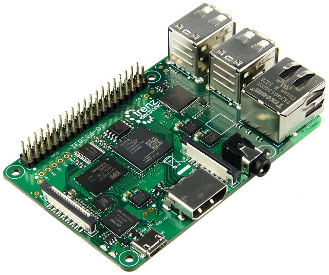
Earlier this year, I wrote about Trenz Electronic’s Xilinx Zynq Ultrascale+ system-on-module, but I’ve just found out I missed another interesting product
Source: Meet Zynqberry, a Xilinx Zynq FPGA Board with Raspberry Pi 2/3 Form Factor – CNX Software
Interfacing RGB LED Strip with Arduino with Fade & Color Effect
Using Raspberry Pi GPIO Pins With the RPi.GPIO Python Library
How to Run Arduino Code & Programs on Raspberry Pi
Raspberry Pi is an amazing minicomputer, and I would love to use it in some projects. There is just one tiny problem. I have little to no experience with Python. I used to do some Python coding a few years ago but only the basics. I’m more experienced in C++, specifically writing programs for Arduino. Wouldn’t it be nice if there was some way for those of us to utilize our Arduino programming skills on Raspberry Pi? Luckily, there is!
In this article, you will learn how to run sketches written for Arduino on Raspberry Pi! To achieve this, we will use RasPiArduino framework. That will allow us to compile the Arduino code into binaries which can run on Raspberry Pi. But before we can do that, we have to prepare a few things, both in the Arduino IDE and on Raspberry Pi.
Hardware
- Raspberry Pi 3 Model B
Software
- Arduino IDE
- RasPiArduino framework – https://github.com/me-no-dev/RasPiArduino
- MobaXterm – https://mobaxterm.mobatek.net/
Development Boards | Espressif Systems
ESP32-DevKitC
How to Debounce switches on the Arduino?
POSSIBLE SOLUTIONS
There are many ways to work around this problem, here are 2 simple ones, with their pros and cons:
-
Using a simple “delay()” function.
-
Using the “millis” function.
Using a simple “Delay()” Function
The way this works is when you start pressing the switch the first time the Arduino detects the desired state (LOW in this case) the delay() is started and waits between 50 and 200 milliseconds, this pauses the entire code on the Arduino until the delay is expired.
The reasoning is that the delay will be long enough to not let the Arduino read the bouncing and only register one switch press.
This method works fairly well but there are pros and cons:
Cons:
-
The delay() function is a ‘blocking’ function, freezing the execution of the Arduino code, so that when the delay is started nothing else can be done, such as reading a sensor or displaying values on an LCD, until the delay is expired.
-
It can’t be used inside Interrupts.
Pros:
-
Requires less coding than the millis() function and doesn’t need variables.
-
Easy to use and adequate for simple projects.
Using the “millis()” Function
The millis() function, when called, returns a time value (in milliseconds) that represent the time passed since the Arduino was powered up.
This timer is started automatically at power up without the need of any coding, so you can just call the function “millis()” to get the current value.
So by using some variables we can know the amount of time passed and use this instead of the delay() function.
The big advantage is that the millis() function is also a “non-blocking function” which means that the Arduino is not paused or frozen, so you can do other things unlike the delay() function which pauses the code completely.
Pros and cons:
Cons:
-
The millis() function requires a bit more coding since it requires variables compare to know how much time as passed.
-
The millis() timer will overflow (reset to zero) after approximately 49 days, no really a problem in most cases but something to keep in mind depending on how you use it.
Pros:
-
Since it doesn’t block or stops the code, you can do other things like check sensors or update display.
-
Can be used inside interrupts unlike the delay() function.
-
Useful for accurate timing of actions inside projects.
CONNECTIONS
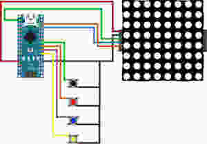

In this tutorial we will be connecting 4 tact switches.
The black one will demonstrate switch bouncing.
The red and blue will show the delay() and millis() functions.
The yellow one will reset the LED Matrix counter.
THE CODE
All the switches are using the Arduino INPUT_PULLUP resistors to set their un-pressed state to HIGH.
We are also using some button state variables to make sure that when a switch is pressed and held down, the counter does not keep increasing.
Both the delay() and millis() function have a value of 100ms for debounce.
As always please watch the tutorial video for more information.
/* Arduino Switch Debounce Examples

Created by Yvan / https://Brainy-Bits.com

This code is in the public domain...

You can: copy it, use it, modify it, share it or just plain ignore it!
Thx!

*/

// Needed for the LED Matrix
#include <MD_Parola.h>
#include <MD_MAX72xx.h>
#include <SPI.h>

#define HARDWARE_TYPE MD_MAX72XX::ICSTATION_HW
/*  PAROLA_HW,    ///< Use the Parola style hardware modules.
    GENERIC_HW,   ///< Use 'generic' style hardware modules commonly available.
    ICSTATION_HW, ///< Use ICStation style hardware module.
    FC16_HW       ///< Use FC-16 style hardware module.
*/

//Pins from the LED Matrix to the Arduino
#define MAX_DEVICES 1
#define CLK_PIN   13
#define DATA_PIN  11
#define CS_PIN    10

//Switches pins connected to Arduino
#define switchpinBlack 6
#define switchpinRed 5
#define switchpinBlue 4
#define switchpinYellow 3

// Variable used for millis debounce
long TimeOfLastDebounce = 0;  // holds the last time the switch was pressed
long DelayofDebounce = 100;  // amount of time that needs to be experied between presses

// Variable used to save the state of the switches
// Needed so the counter only goes +1 for each keypress

int BlackButtonState = 0;
int RedButtonState = 0;
int BlueButtonState = 0;

// Variable to hold the value of the counter
int displaycounter=0;

// Hardware SPI connection
MD_Parola P = MD_Parola(HARDWARE_TYPE, CS_PIN, MAX_DEVICES);


void setup(void)
{
  P.begin();
  P.setTextAlignment(PA_CENTER);

//All switches use the Arduino input pullup resistors
  pinMode(switchpinBlack, INPUT_PULLUP);
  pinMode(switchpinRed, INPUT_PULLUP);
  pinMode(switchpinYellow, INPUT_PULLUP);
  pinMode(switchpinBlue, INPUT_PULLUP);
}

void loop(void)
{
    // Black Switch - No Debounce
    if (digitalRead(switchpinBlack) == LOW && BlackButtonState == 0) {
      BlackButtonState=1;
      displaycounter++;
      P.print(displaycounter);
    } else {
      if (BlackButtonState == 1 && digitalRead(switchpinBlack) == HIGH) {
        BlackButtonState=0;
      }
    }


    // Red Switch - Debounce using a delay() command
    if (digitalRead(switchpinRed) == LOW && RedButtonState == 0) {
      delay(100);  // The higher the Delay the less chance of bouncing
      RedButtonState=1;
      displaycounter++;
      P.print(displaycounter);
    } else {
      if (RedButtonState == 1 && digitalRead(switchpinRed) == HIGH) {
        RedButtonState=0;
      }
    }


    // Blue Switch - Debounce using a 'millis' timer
    if (digitalRead(switchpinBlue) == LOW && BlueButtonState == 0) {

      // check if enough time has passed to consider it a switch press
      if ((millis() - TimeOfLastDebounce) > DelayofDebounce) {
        BlueButtonState=1;
        displaycounter++;
        TimeOfLastDebounce = millis();
        P.print(displaycounter);
      }
    } else {
      if (BlueButtonState == 1 && digitalRead(switchpinBlue) == HIGH){
        BlueButtonState=0;
      }
    }

    // Yellow Switch - Reset Counter
    if (digitalRead(switchpinYellow) == LOW) {
      displaycounter=0;
    }
  }
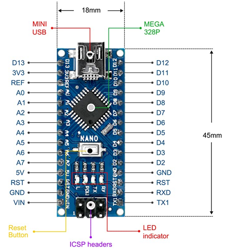
LAFVIN Nano V3.0, Nano Board ATmega328P 5V 16M Micro-Controller Board Compatible with Arduino IDE