Source: Slic3r Manual – Overview
Category Archives: 3dprinting
Making Parametric Models In Fusion 360
We all know and love OpenSCAD for its sweet sweet parametrical goodness. However, it’s possible to get some of that same goodness out of Fusion 360. To do this we will be making a mathematical mode…
Print Quality Guide
Source: Print Quality Guide
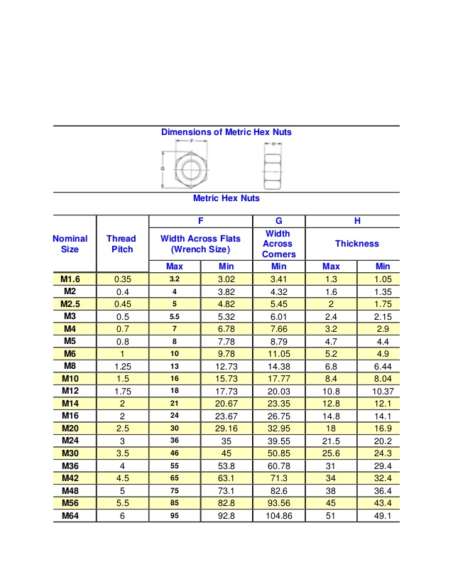
Dimension of Metric Hex Nuts
Metric Flat Square Nut Dimensions
How to Make a USB Laptop Keyboard Controller
How to Make a USB Laptop Keyboard Controller : This Instructable will provide a step by step procedure for building a USB laptop keyboard and touchpad controller. I created this guide and video to hopefully make it easier for people to re-purpose an old laptop. A typical laptop keyboard relies o…
3D Printer G-code Commands List & Tutorial | All3DP
Understanding G-code commands is the key to your 3D printer. Quickly learn this code using our tutorial. Includes a list of all commands.
Universal bitting depth key decoding utility | kstoerz.com
Prusa Knowledge Base | Bed Level Correction
This calibration is for advanced users only!
Together with the Mesh Bed Leveling, the Bed Level Correction is an important feature designed to allow users to compensate for even the slightest imperfections in the first layer. It allows to virtually raise or lower the heatbed on the Left, Right, Front and Back sides, essentially enabling you to have a different Live Adjust Z value on each of the four sides of the heatbed. This feature is most beneficial if you frequently need to use the entire area of the heatbed.
Before you start the calibration, make sure there is nothing between the steel sheet and the heatbed.
How to use Bed Level Correction
Starting from firmware 3.5.2, the adjustment limit is +/- 100 microns (μm) instead of +/- 50 microns (μm) in the previous versions. Even 20 microns can make a huge difference, so when using this function, make small incremental changes. Just like in the Live-Z adjust, negative values lower the nozzle closer to the heatbed.
Before we begin, clean the entire surface of your heatbed with 90% (or more) isopropyl alcohol.
- Run a First Layer Calibration to get a good baseline calibration.
- Download and slice this test model for your printer version using the Prusa Slicer’s default PLA settings, 0.20 mm layer height.
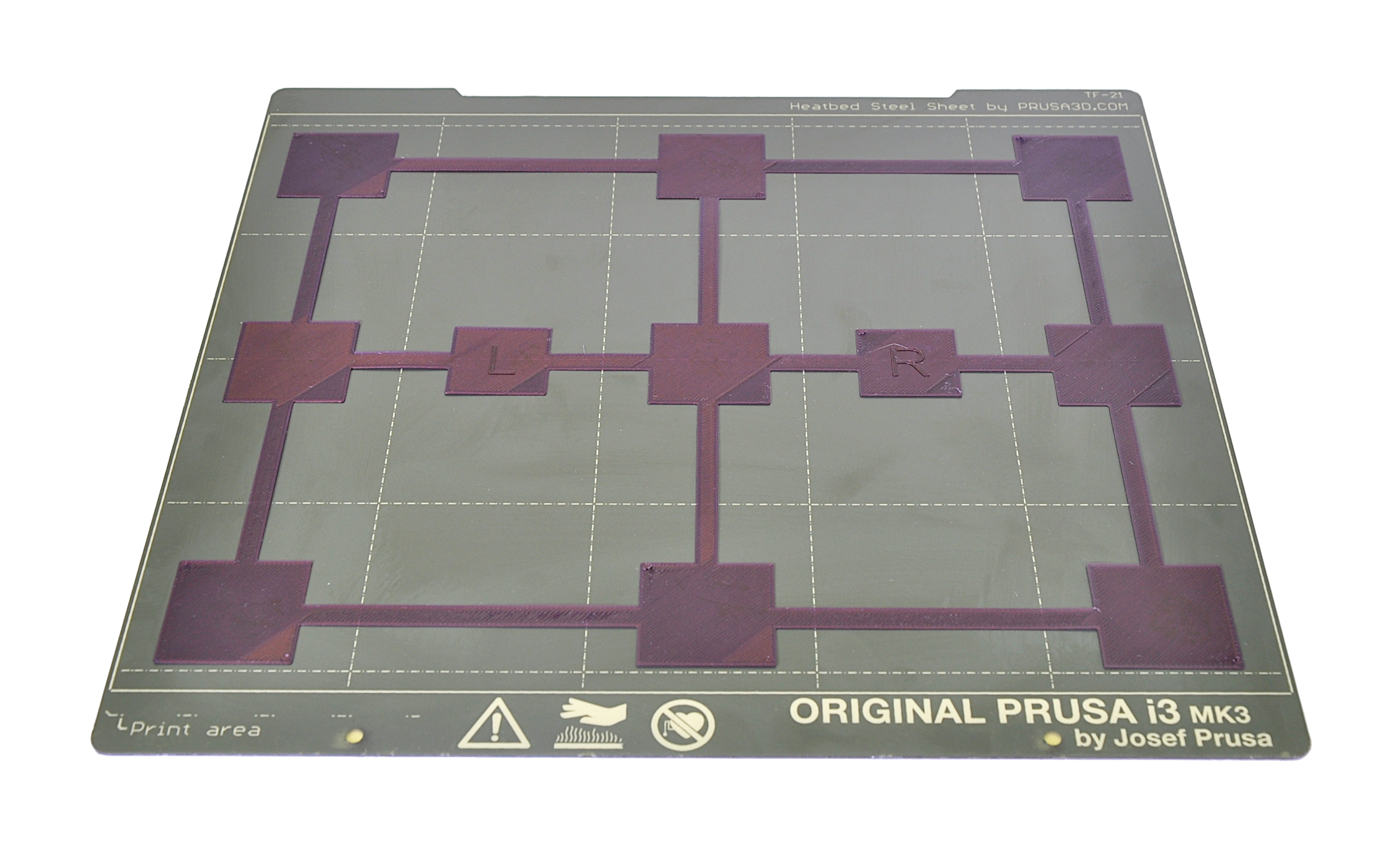
- Print the g-code prepared in the previous step with a PLA filament (ideally light and opaque color). The print is just one layer high and takes up most of the printable surface. You do not have to print the entire file, stop the print as soon as the differences in layer height across the plate are obvious.
- Evaluate where the layer is too squished and full of scars and where there are gaps in between the lines. In the photo below, the lines are way too squished in the top-right corner, and the nozzle is too far away in the bottom-left.
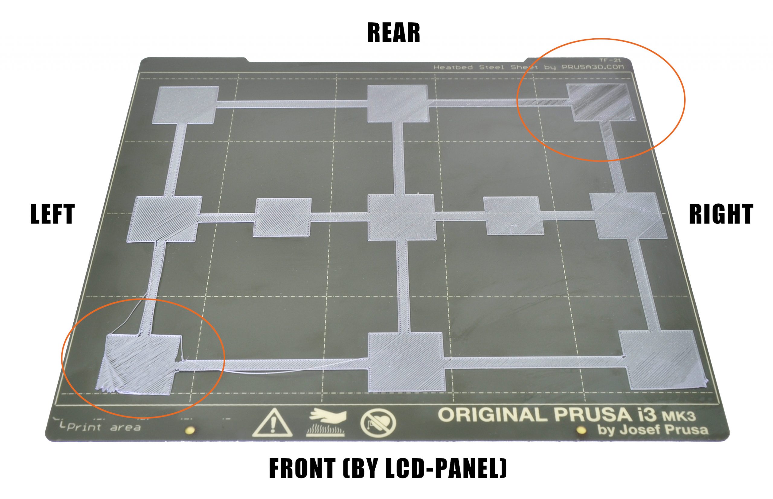
In the example above you want to adjust a minus-value on the left, bringing the nozzle closer and a plus-value on the right, moving the nozzle away. You may also need to adjust the distance front and back, but do a test print after adjusting the left and right side.
- Go to the LCD Menu -> Calibration -> Bed level correction. There, you can adjust Left/Right/Front/Rear values (understood from your point of view, as you are looking at the printers LCD).
- Edit the values, we suggest going in steps of +/- 10. These values will be added to the baseline Live Z value set in step 1. Remember, a negative value will decrease the distance between the nozzle making the layer more squished. A positive value will increase the nozzle-bed distance, curing the scars on your first layer.
- Repeat steps 3 to 6 until you are satisfied with the result (photo below for inspiration).
For example, let’s say your Live adjust Z value is -1.000 and that the layer is too squished in the rear and that you see gaps between the lines on the right side.
- Rear: you need to enter a positive value (at the end it will be 25 for example) to make the layer less squished
- Right: you need to enter a negative value (at the end it will be -10 for example) to make the layer more squished
The Bed Level Correction values are reset to 0 every time you start the Calibration Wizard or the XYZ calibration. Once you find your ideal values, write them down as a backup.
– Repetier Software
Corona Virus banner illustration – Microbiology And Virology Concept – by Mike Fouque 1 Object Placement Import one or more 3D models and place, scale, rotate or duplicate them on your virtual bed. 2 Slice Slice your plate with different Continue reading →
Source: – Repetier Software