All posts by smarc
tapnair/Project-Archiver: Fusion 360 Export Utility
dekuNukem/duckyPad: Do-It-All Mechanical Macropad
J1772 Charge Protocol
http://www.fveaa.org/fb/J1772_386.pdf
OpenEVSE
Electric Vehicle Charging
J1772 / OpenEVSE
Electric Vehicle Charging
J1772 / OpenEVSE
Presented by:
Chris Howell
OpenEVSE
Topics:
• Electric Vehicle Supply Equipment
• J1772 Recommended Practice
• Challenges
• OpenEVSE
• Technology Development
OpenEVSE
Electric Vehicle Supply Equipment (EVSE)
The EVSE provides a safe connection from the
Electrical source to the Plug in Vehicle.
The EVSE provides several safety features:
• Power pins not hot until EVSE‐EV negotiation
• Ground Fault Circuit Interrupt (GFCI)
• Graceful start‐up/shut‐down
• Ground verification
• Pilot signal detection and verification
• Stuck Relay detection
• Plug rated for many plug‐in /disconnect cycles
*Not All EVSE implement every feature
OpenEVSE
J1772 is a SAE Recommended Practice for a electric vehicle conductive
charge system which covers:
• General physical
• Electrical
• Performance requirements
The intent is to define a common electric vehicle charging system
architecture including operational requirements and the functional and
dimensional requirements for the vehicle inlet and mating connector.
J1772 Overview
OpenEVSE
OpenEVSE
Charge Level Voltage Max Current
Level 1 (L1) 120VAC 16A ‐ 1.9kw
Level 2 (L2) 208 ‐ 240VAC 80A ‐ 20kw
DC Level 1 (L3) 200 – 500V DC 80A – 40kW
DC Level 2 (L3) 200 – 500V DC 200A ‐ 100kW
• Pilot Signal – 1khz pilot to communicate EVSE – EV state
• Duty Cycle – EVSE defines the maximum current available to the EV
• Proximity – Allows for graceful start‐up and shutdown of current flow
J1772 Properties
OpenEVSE
Charge Level Voltage Max Current
Level 1 (L1) 120VAC 16A ‐ 1.9kw
Level 1 Charging
• Adds < 5 Miles per every hour charging
• Best suited for Plug‐in‐Hybrid with low EV range
• Painfully slow for most BEVs
• Great in location where EVs park for several days at time and
high density is desired such as Airport
OpenEVSE
Charge Level Voltage Max Current
Level 2 (L2) 208 – 240VAC 80A ‐ 20kw
Level 2 Charging
• Adds up to 62 Miles range per hour of charge
• Rate Limited by on‐board charger of vehicle
• Slightly more costly than L1
• Great in location where Plug‐ins park. Home – Work –
Malls ‐ Attractions
OpenEVSE
Charge Level Voltage Max Current
Level 3 (DC‐FC) 300 – 460VDC 250A+
Level 3 Charging
• Adds up to 300 Miles range per hour of charge
• Much more costly than L1/L2
• Several competing standards (CHAdeMO, J1772, Tesla)
• Requires 3 Phase AC infrastructure
• Great in location between cities, near the highway and
where recharge speed is important
OpenEVSE
Charging Placement
• Charging Stations in prime locations
tend to be “ICE”d, locate close to
power but in less desirable parking
locations
• Charging speed should match time
at location, less time spent = quicker
chargers. Fast food – DCQC… Airport
long term L1
• Place EVSE between spaces so 1
EVSE can service 2 – 4 spaces each.
• Good Signage ‐ Reserved for plug‐in
OpenEVSE
State Pilot High Pilot Low Frequency EV Resistance Description
State A +12V N/A DC N/A Not Connected
State B +9V ‐12V 1000hz 2.74k EV Connected
(Ready)
State C +6V ‐12V 1000hz 882 EV Charge
State D +3V ‐12V 1000hz 246 EV Charge
Vent. Required
State E 0V 0V N/A Error
State F N/A ‐12V N/A Unknown/Error
The J1772 Pilot is a 1khz +12V to ‐12V square wave, the voltage
defines the state. The EV adds resistance pilot to Ground to vary the
voltage. The EVSE reads the voltage and changes state accordingly.
J1772 Pilot Signal
OpenEVSE
Amp Duty Cycle Amp Duty Cycle
6A 10% 40A 66%
12A 20% 48A 80%
18A 30% 65A 90%
24A 40% 75A 94%
30A 50% 80A 96%
The J1772 Pilot is a 1khz +12V to ‐12V square wave, the Duty cycle
(ratio high state to low state) determined the maximum available
current. The EVSE sets the duty cycle the EV must comply to original
setting or changes to the duty cycle.
J1772 Duty Cycle
6A ‐ 51A
Amps = Duty cycle x 0.6
Duty cycle = Amps / 0.6
51A ‐ 80A
Amps = (Duty Cycle ‐ 64) 2.5
Duty cycle = (Amps / 2.5) + 64
OpenEVSE
J1772 Negotiation
OpenEVSE
The J1772 Proximity circuit is present in the
Electric Vehicle and the J1772 plug. It uses a
voltage divider circuit with resistors in Parallel and
series to achieve different measured voltages for
each state.
J1772 Proximity
State Voltage on
Proximity pin
Not Connected 4.5v
Button Pressed 3.0v
Connected 1.5v
Resistance
R4 330
R5 2700
R6 150
R7 330
OpenEVSE
J1772 Proximity
State Voltage on
Proximity pin
Not Connected 4.5v
Voltage Divider
Resistance
R4 330
R5 2700
R6 150
R7 330
OpenEVSE
J1772 Proximity
State Voltage on
Proximity pin
Button Pressed 3.0v
Resistance Series Resistance Parallel
Voltage Divider
Resistance
R4 330
R5 2700
R6 150
R7 330
OpenEVSE
J1772 Proximity
State Voltage on
Proximity pin
Connected 1.5v
Resistance Series Resistance Parallel
Voltage Divider
Resistance
R4 330
R5 2700
R6 150
R7 330
OpenEVSE
J1772 Plug
OpenEVSE
J1772 Connector
OpenEVSE
Challenges
• Incompatibility of devices
• Missing safety features (Diode check, Vent required state)
• Poor quality of devices
• Overheating at or below rated current
• Cost of deployment
• Devices to bypass/circumvent/ignore J1772 NEC requirements
OpenEVSE
Home Built or Commercial Product???
Almost touching….
Hints:
• Device has cord but
no fuses
• Device uses wrong
type of relays (SSR not
Mechanical)
• Poor construction
• Metal Shavings
OpenEVSE
Hints:
• Open Source LINUX board
• Thermal issues at/below rated power
• Off the shelf power meter inside
• High percentage out of order, on the blink.
• Improper crimp on Power Connector
Home Built or Commercial Product???
OpenEVSE
Newer EVs capable of drawing higher
current are causing problems for even
UL listed commercial EVSEs running at
or below their rated limit.
• Honda first to implement cutoff in
the inlet
OpenEVSE
Don’t try this at home…
Ignoring J1772, NEC, Local code etc. can be
hazardous to people and property
The pictured solutions are work around to
bypass/trick J1772 protections
• No relay to remove power from connecter
• No GFCI protection
• Must be connected in certain order with
quick timing
• Causes vehicle error codes
• Could cause damage to charging system
OpenEVSE
Warnings
OpenEVSE hardware/firmware is intended for use for ENGINEERING
DEVELOPMENT, DEMONSTRATION, OR EVALUATION PURPOSES ONLY and is
NOT considered to be a finished end‐product fit for general consumer use.
OpenEVSE
• Source materials (source code, schematics, recipes, documents) are
published and made available to the public
• Enables anyone to copy, modify and redistribute without paying royalties
or fees.
• Open‐source code can evolves through community cooperation
“Open Source”
OpenEVSE
OpenEVSE Source code is licensed open source under GNU GPLv3
Nobody should be restricted by the software they use. There are four
freedoms that every user should have:
• the freedom to use the software for any purpose,
• the freedom to change the software to suit your needs,
• the freedom to share the software with your friends and neighbors, and
• the freedom to share the changes you make.
http://www.gnu.org/licenses/gpl.html
GNU GPL v3
OpenEVSE
Creative Commons Attribution‐ShareAlike 3.0
All other OpenEVSE content licensed under CC BY SA 3.0
OpenEVSE
OpenEVSE is a Open Source Electric Vehicle J1772
Charging Station Controller
• Both Hardware and Firmware Open Source
• Fully supports SAE J1772 Recommended Practice
• Software adjustable pilot (6A – 80A)
• Built in GFCI with 20ma trip point
• Supports all J1772 states including “ventilation
required”
• Supports Diode check
• AC L1 – L2 auto detect Current setting for each
• Ground verification and Stuck Relay detection
OpenEVSE
OpenEVSE
February 13, 2011 ‐ Experiments with pilot began
June 15, 2011 – Nissan LEAF Delivered
July 1, 2011 – Successfully Charged LEAF
July 2011 – Joined forces with Lincomatic
October 2011 – Started OpenEVSE open sourced
hardware and firmware
December 2011 – First prototype OpenEVSE boards
available
OpenEVSE
OpenEVSE Plus
OpenEVSE Plus
• Board and Schematic Files Available
• Available in limited quantities as Kit or Built
• All surface mount component work complete
• Firmware pre‐loaded
• Tiny 2.2 x 1.75
• Power Supply Integrated
• Inexpensive ‐ $135 (kit) $155 (Built)
OpenEVSE
OpenEVSE LCD
OpenEVSE RGB LCD
• Board and Schematic Files Available
• Basic or with Real Time Clock (RTC)
• RTC adds EVSE based timer support
• Optional button adds LCD Menu Interface
• Available in limited quantities as Kit or Built
• All surface mount component work complete
• Basic $30 (kit) $40 (Built)
• RTC $40 (kit) $50 (Built)
OpenEVSE
OpenEVSE DIY
OpenEVSE DIY boards
• Board and Schematic Files Available
• Board available in OSHpark Store
• Source your own components
• Build yourself
• 3.4 x 2.5
• Inexpensive ‐ Board and PS ~ $100
OpenEVSE
Example EVSE built with OpenEVSE
• Diversified Stage Enclosure
• 30A ITT/Leviton J1772 Cable
• OpenEVSE Plus
• OpenEVSE RGB LCD with RTC
OpenEVSE
OpenEVSE is based on the ATMEL AVR:
• 8‐bit microprocessor
• 16mhz
• Compatible with Arduino IDE
OpenEVSE CPU
OpenEVSE
• The OpenEVSE pilot uses a 1w DC/DC converter to generate +12v and ‐12v.
• The Opamp takes the 1khz pilot from the microprocessor 0 – 5v and switched ‐
12v to +12v.
• The pilot is read by the microprocessor, R5 – R6 – R7 scale the ‐12v ‐ +12v signal
to 0 – 5v.
OpenEVSE Pilot
OpenEVSE
GFCI measures the difference of current going in vs. current going out. The circuit
“trips” if an imbalance of > 20ma. The trip point can be adjusted by modifying the
burden resistor R17 or the ratio of R14 – R15. The output of the fault line is
monitored by the microprocessor as an interrupt.
OpenEVSE GFCI
OpenEVSE
OpenEVSE uses 2 MID400 Optical Isolators to detect the presence of voltage on each
Hot line by sending a small current to ground. The AC_Test leads are connected after
the power relay to allow stuck relay detection as well as Ground Verification and
L1/L2 auto‐detection (1/3 Phase detection in Europe).
OpenEVSE Power
1 2
L L L2
L H L1
H L L1
H H Bad Ground
OpenEVSE
The relay circuit uses 2 2222 NPN transistors to switch 12V to the relay(s). Beginning
in 2.0B2 OpenEVSE supports both 1 DPST or 2 SPST. Using 2 relays allows the self tests
to be run one leg at a time avoiding powering the J1772 handle during the test. Also
power can be removed from 1 leg if there is a stuck relay condition.
OpenEVSE Relay
OpenEVSE
Coming Soon (hopefully) / Areas you can contribute
• Simple Communications Protocol
• Android App
• Raspberry Pi integration
• Wi‐Fi support
• Vehicle info to EVSE ‐ CAN / WiFi
• LCD touch screen
• Energy Monitoring
• General code clean up
• RTC / Timer code library
OpenEVSE
Simple Communications protocol
• Work in conjunction with existing Command Line Interface
• Work in progress / High Priority
https://docs.google.com/document/d/1e00CnEpSUb6BpQho9srvDj8HuKcuV
MxiXaSICXDvHeA/edit?usp=sharing
• EVSE Status and Control
• Energy Monitoring input
• Data from EV via CAN or WiFi (TESLA REST API)
• Needed for Android App, LCD touchscreen / Raspberry pi
• UART / I2C ‐ Wifi / Bluetooth
OpenEVSE
L1 and L2 EVSEs are currently dumb devices
• No ‐ 2 way data communication between EV and EVSE
• Data can be provided to EVSE via
• CAN bus
• Wifi/3G/4G
• Bluetooth
• EV – EVSE communication allows
EVSE to know and act on:
• State of Charge
• Battery Voltage
• Current
OpenEVSE
Android App
• Tablet/Phone
• Touchscreen for EVSE
• Fusion EVSE and EV info/control
• Serial SPP or WiFi
OpenEVSE
Raspberry Pi
• Inexpensive method to add Ethernet /
Wi‐Fi etc.
• Web front end to EVSE
• Fusion EVSE and EV info/control
• TTL Serial or I2C
• Headless or LCD Touchscreen
OpenEVSE
WiFi
• Telnet/SSH access to SerialCLI (Done)
• Web client – provide input to webserver
• Fusion EVSE and EV info/control
• TTL Serial
• Con – twice as expensive as adding Raspberry pi
OpenEVSE
Simple LCD touchscreen
• Arduino Touch Screens
• 4D Systems
• Fusion EVSE and EV info/control
• TTL Serial or I2C
OpenEVSE
Energy Monitoring
• Based on Open Energy Monitor
• Reads both Voltage and Current
• May not be necessary if data can be obtained from
EV
• TTL Serial or I2C
OpenEVSE
Modifications to J1772 inlet and/or handle can provide
information to the EV/EVSE to act on over temp conditions and
reduce current or terminate charge.
OpenEVSE
Infrastructure is expensive, Smart EVSEs could
share a circuit and share load.
• J1772 allows for dynamic current settings
• Vehicles with low current requirement of
those finished can give capacity to those
who need it
Example: 8 ‐ 30A EVSE
1 30A 5 16A
2 30A 6 13A
3 26A 7 11A
4 20A 8 10A
OpenEVSE
Resources:
Main Project Page:
http://www.openevse.com
http://code.google.com/p/open‐evse/
Discussion
https://groups.google.com/forum/?fromgroups#!forum/OpenEVSE
http://www.mynissanleaf.com/viewtopic.php?f=26&t=6546
Development Code
https://github.com/lincomatic/open_evse
OpenEVSE
Questions??? / Demos…
Nvidia Drivers on Linux Mint
If drivers fail to load at boot
Your machine boots up with a low-resolution screen, and and after logging in you see an error message to the effect of “Your system is currently running without video acceleration. You may experience poor performance and high CPU usage“.
There should also be a button to launch the driver manager.
If you’re unable to change things via the driver manager:
From a shell: edit /etc/modules
Make sure the following three lines are there – if not, add them to the bottom of the file:
nvidia

nvidia-drm

nvidia-modeset
Then reboot.
If that doesn’t work, you can see what the system uses with
ubuntu-devices list
You can use ubuntu-devices autoinstall which should do the job.
Reboot when complete.
Or you can install a specific driver version with
apt install nvidia-driver-470 (or what ever version you need). You can use ubuntu-devices list to see available choices. Reboot when complete.
To remove the driver and its associated dependencies, use apt.
Ex.
sudo apt remove nvidia-driver-470 then use the open-source nouveau driver.
sudo apt autoremove
Then reboot. It should
You can install the open-source driver to revert to the open-source driver:
sudo apt install xserver-xorg-video-nouveau
Then reboot
Home · espressif/ESP8266_AT Wiki
Source: Home · espressif/ESP8266_AT Wiki
ESP8266 – AT Command Reference · room-15
ESP8266 – AT Command Reference
ESP8266, in it’s default configuration, boots up into the serial modem mode. In this mode you can communicate with it using a set of AT commands. AT commands that ESP8266 supports, explain what they do and how to use them.
Historically AT commands are based on the Hayes Command Set and these are no different.
AT Commands
Index of all known AT commands
Line termination
ESP8266 expects <CR><LF> or CarriageReturn and LineFeed at the end of each command, but just<CR> seems to work too.
Command variants
Each command can have up to 4 variants changing the function of it. You can chose between them by appending one of four possible values to the end of the root command itself. These four appendices can have the following values "",=<parameter|[parameters]>,"?",=?
| Type | Example | Description |
|---|---|---|
| Test | AT+CIPSTART=? | Query the range of values (So far only AT+CWMODE=? uses it) |
| Query | AT+CMD? | Returns the current value of the parameter. |
| Set | AT+CMD=Parameter | Set the value of user-defined parameters in commands and run. |
| Execute | AT+CMD | Runs commands with no user-defined parameters. |
Note:
- Not all AT commands support all 4 variants.
- [] = default value, not required or may not appear.
- String values require double quotation marks, for example:
AT+CWSAP="ESP756190","21030826",1,4. - Baud rate = 115200
- AT instruction ends with “\r\n”
Commands
AT – Test AT startup
| Variant | Command | Response | Function |
|---|---|---|---|
| Execute | AT | OK | Test if AT system works correctly |
AT+RST – Restart module
| Variant | Command | Response | Function |
|---|---|---|---|
| Execute | AT+RST | OK | Reset the module |
ESP-01 Output after reset:
 ets Jan  8 2013,rst cause:4, boot mode:(3,7)

wdt reset
load 0x40100000, len 24444, room 16
tail 12
chksum 0xe0
ho 0 tail 12 room 4
load 0x3ffe8000, len 3168, room 12
tail 4
chksum 0x93
load 0x3ffe8c60, len 4956, room 4
tail 8
chksum 0xbd
csum 0xbd

ready
ESP-12 Output after reset:
\0x04B1\0x85 \0xff\0x13:'\0xe0;\0xcc;!G\0xfa\0x11\0xa9R\0xc6\0x83\0x01\0xd9\0x81
[Vendor:www.ai-thinker.com Version:0.9.2.4]

ready
AT+GMR – View version info
| Variant | Command | Response | Function |
|---|---|---|---|
| Execute | AT+GMR | version, OK |
Print firmware version |
Parameters:
version: firmware version number
ESP-01 output:
00160901
ESP-12 output:
0018000902-AI03
AT+GSLP – Enter deep-sleep mode
| Variant | Command | Response | Function |
|---|---|---|---|
| set | AT+GSLP=time |
time OK |
Enter deep sleep mode for time milliseconds |
parameters:
time: Time to sleep in milliseconds
Example:
AT+GSLP=1500
Note:
Hardware has to support deep-sleep wake up (Reset pin has to be High).
ATE – Enable / Disable echo
| Variant | Command | Response | Function |
|---|---|---|---|
| Execute | ATE0 | OK | Disable echo (Doesn’t send back received command) |
| Execute | ATE1 | OK | Enable echo (Sends back received command before response) |
Note:
I haven’t had any luck with this command yet. Both ATE0 and ATE1 return no this fun.
ATE returns OK
This changed with ESP-12 where the command functions exactly as expected!
AT+CWMODE – WIFI mode(station, AP, station + AP)
| Variant | Command | Response | Function |
|---|---|---|---|
| Test | AT+CWMODE=? | +CWMODE:(1-3) OK | List valid modes |
| Query | AT+CWMODE? | +CWMODE:mode OK |
Query AP’s info which is connect by ESP8266. |
| Execute | AT+CWMODE=mode |
OK | Set AP’s info which will be connect by ESP8266. |
Parameters:
mode: An integer designating the mode of operation either 1, 2, or 3.
1 = Station mode (client)
2 = AP mode (host)
3 = AP + Station mode (Yes, ESP8266 has a dual mode!)
Notes:
ESP-12 came configured as host with ssid set to ESP_A0A3F2, no password, channel 1 You can use AT+CWSAP? to find the current settings.
AT+CWJAP – Connect to AP
| Variant | Command | Response | Function |
|---|---|---|---|
| Query | AT+CWJAP? | + CWJAP:ssid OK |
Prints the SSID of Access Point ESP8266 is connected to. |
| Execute | AT+CWJAP=ssid,pwd |
OK | Commands ESP8266 to connect a SSID with supplied password. |
Parameters:
ssid:String, AP’s SSIDpwd:String, not longer than 64 characters
Example:
AT+CWJAP="my-test-wifi","1234test"
Example AT+CWJAP?:
+CWJAP:"my-test-wifi"
AT+CWLAP – Lists available APs
| Variant | Command | Response | Function |
|---|---|---|---|
| Set | AT+CWLAP=ssid,mac,ch |
+CWLAP:ecn,ssid,rssi,mac OK |
Search available APs with specific conditions. |
| Execute | AT+CWLAP | AT+CWLAP:ecn,ssid,rssi,mac OK |
Lists available Access Points. |
Parameters:
ecn:- 0 = OPEN
- 1 = WEP
- 2 = WPA_PSK
- 3 = WPA2_PSK
- 4 = WPA_WPA2_PSK
ssid: String, SSID of APrssi: signal strengthmac: String, MAC address
Note:
On ESP-01 I have had no luck with the set version of this command (AT+CWLAP=...). If you know what it does please let me know.
On ESP-12, the Set version of the command allows to see if a certain SSID, with certain MAC on certain channel exists. If it doesit is returned as one line of the Execute version of this command.
Example AT+CWLAP:
+CWLAP:(3,"CVBJB",-71,"f8:e4:fb:5b:a9:5a",1)
+CWLAP:(3,"HT_00d02d638ac3",-90,"04:f0:21:0f:1f:61",1)
+CWLAP:(3,"CLDRM",-69,"22:c9:d0:1a:f6:54",1)
+CWLAP:(2,"AllSaints",-88,"c4:01:7c:3b:08:48",1)
+CWLAP:(0,"AllSaints-Guest",-83,"c4:01:7c:7b:08:48",1)
+CWLAP:(0,"AllSaints-Guest",-83,"c4:01:7c:7b:05:08",6)
+CWLAP:(4,"C7FU24",-27,"e8:94:f6:90:f9:d7",6)
+CWLAP:(2,"AllSaints",-82,"c4:01:7c:3b:05:08",6)
+CWLAP:(3,"QGJTL",-87,"f8:e4:fb:b5:6b:b4",6)
+CWLAP:(4,"50EFA8",-78,"74:44:01:50:ef:a7",6)
+CWLAP:(0,"optimumwifi",-78,"76:44:01:50:ef:a8",6)
+CWLAP:(3,"BHQH4",-95,"18:1b:eb:1a:af:5b",6)
+CWLAP:(3,"NETGEAR49",-86,"84:1b:5e:e0:28:03",7)
+CWLAP:(3,"ngHub_319332NW00047",-56,"20:e5:2a:79:b1:2f",11)
+CWLAP:(3,"BFZR4",-73,"18:1b:eb:1d:c3:91",11)
+CWLAP:(1,"5FFVL",-82,"00:26:b8:b5:c0:f2",11)
+CWLAP:(3,"59G6D",-77,"00:7f:28:6d:91:7b",11)
+CWLAP:(3,"N16FU",-53,"20:cf:30:ce:60:fe",11)
+CWLAP:(3,"ITS",-82,"90:72:40:21:5f:76",11)
+CWLAP:(3,"ITS",-79,"24:a2:e1:f0:04:e4",11)
Example AT+CWLAP="N16FU","20:cf:30:ce:60:fe",11:
+CWLAP:(3,"N16FU",-53,"20:cf:30:ce:60:fe",11)
AT+CWQAP – Disconnect from AP
| Variant | Command | Response | Function |
|---|---|---|---|
| Execute | AT+CWQAP | OK | Disconnect ESP8266 from the AP is currently connected to. |
Note:
After running this command, if you run AT+CWJAP? it still shows the AP you were connected to before. Back to Index
AT+CWSAP – Configuration of softAP mode
| Variant | Command | Response | Function |
|---|---|---|---|
| Query | AT+CWSAP? | +CWSAP:ssid,pwd,ch,ecn OK |
Query configuration of ESP8266 softAP mode. |
| Set | AT+CWSAP=ssid,pwd,ch,ecn |
OK | Set configuration of softAP mode. |
Parameters:
ssid: String, ESP8266’s softAP SSIDpwd: String, Password, no longer than 64 charactersch: channel idecn:- 0 = OPEN
- 2 = WPA_PSK
- 3 = WPA2_PSK
- 4 = WPA_WPA2_PSK
Example
AT+CWSAP="esp_123","1234test",5,3
AT+CWSAP? => +CWSAP:"esp_123","1234test",5,3
AT+CWLIF – List clients connected to ESP8266 softAP
| Variant | Command | Response | Function |
|---|---|---|---|
| Execute | AT+CWLIF | [ip,other] OK |
List information on of connected clients. |
Parameters:
ip: IP address of a client connected to the ESP8266 softAP other: Other info, look at example. I don’t know what it means yet.
Example (ESP-01):
AT+CWLIF

192.168.4.100,3fff50b4:3fff50ba:3fff50c0:3fff50c6:3fff50cc:3fff50d2

OK
Example (ESP-12):
AT+CWLIF

192.168.4.100,c0:ee:fb:25:33:ec

OK
I ran the command after connecting to the ESP8266 with my cellphone.
AT+CWDHCP – Enable/Disable DHCP
| Variant | Command | Response | Function |
|---|---|---|---|
| Set | AT+CWDHCP=mode,en |
OK | Enable or disable DHCP for selected mode |
Parameters:
mode:- 0 : set ESP8266 as a softAP
- 1 : set ESP8266 as a station
- 2 : set both ESP8266 to both softAP and a station
en:- 0 : Enable DHCP
- 1 : Disable DHCP
Note:
This command doesn’t seem to work on firmware 00160901 (ESP-01) nor 0018000902-AI03 (ESP-12).
AT+CIPSTAMAC – Set MAC address of ESP8266 station
| Variant | Command | Response | Function |
|---|---|---|---|
| Query | AT+CIPSTAMAC? | +CIPSTAMAC:mac OK |
Print current MAC ESP8266’s address. |
| Execute | AT+CIPSTAMAC=mac |
OK | Set ESP8266’s MAC address. |
Parameters:
mac: String, MAC address of the ESP8266 station.
Example:
AT+CIPSTAMAC="18:aa:35:97:d4:7b"
Note:
This command doesn’t seem to work on firmware 00160901
AT+CIPAPMAC – Set MAC address of ESP8266 softAP
| Variant | Command | Response | Function |
|---|---|---|---|
| Query | AT+CIPAPMAC? | +CIPAPMAC:mac OK |
Get MAC address of ESP8266 softAP. |
| Execute | AT+CIPAPMAC=mac |
OK | Set mac of ESP8266 softAP. |
Parameters:
mac: String, MAC address of the ESP8266 softAP.
Example:
AT+CIPAPMAC=”2c:aa:35:97:d4:7b”
Note:
This command doesn’t seem to work on firmware 00160901
AT+CIPSTA – Set IP address of ESP8266 station
| Variant | Command | Response | Function |
|---|---|---|---|
| Query | AT+CIPSTA? | +CIPSTA:ip OK |
Get IP address of ESP8266 station. |
| Execute | AT+CIPSTA=ip |
OK | Set ip addr of ESP8266 station. |
Parameters:
ip: String, ip address of the ESP8266 station.
Example:
AT+CIPSTA=”192.168.101.108”
Note:
This command doesn’t seem to work on firmware 00160901
AT+CIPAP – Set ip address of ESP8266 softAP
| Variant | Command | Response | Function |
|---|---|---|---|
| Query | AT+CIPAP? | +CIPAP:ip OK |
Get ip address of ESP8266 softAP. |
| Execute | AT+CIPAP=ip |
OK | Set ip addr of ESP8266 softAP. |
Parameters:
ip: String, ip address of ESP8266 softAP.
Example:
AT+CIPAP="192.168.5.1"
Note:
This command doesn’t seem to work on firmware 00160901
AT+CIPSTATUS – Information about connection
| Variant | Command | Response | Function |
|---|---|---|---|
| Test | AT+CIPSTATUS=? | OK | |
| Execute | AT+CIPSTATUS | STATUS:status +CIPSTATUS:id,type,addr,port,tetype OK |
Get information about connection. |
Parameters:
status:- 2: Got IP
- 3: Connected
- 4: Disconnected
id: id of the connection (0~4), for multi-connecttype: String, “TCP” or “UDP”addr: String, IP address.port: port numbertetype:- 0 = ESP8266 runs as a client
- 1 = ESP8266 runs as a server
Note:
On ESP-01 this command returns STATUS:1 instead (no extra info, but status changes) On 0018000902-AI03 this command returns STATUS:2 instead (no extra info, but status changes)
AT+CIPSTART – Establish TCP connection or register UDP port and start a connection
| Variant | Command | Response | Function |
| Set | AT+CIPSTART=type,addr,port |
OK | Start a connection as client. (Single connection mode) |
| Set | AT+CIPSTART=id,type,addr,port |
OK | Start a connection as client. (Multiple connection mode) |
| Test | AT+CIPSTART=? | [+CIPSTART:(id)(“type”),(“ip address”),(port)] OK | List possible command variations) |
Parameters:
id: 0-4, id of connectiontype: String, “TCP” or “UDP”addr: String, remote IPport: String, remote port
AT+CIPSEND – Send data
| Variant | Command | Response | Function |
|---|---|---|---|
| Test | AT+CIPSEND=? | OK | |
| Set | AT+CIPSEND=length |
SEND OK | Set length of the data that will be sent. For normal send (single connection). |
| Set | AT+CIPSEND=id,length |
SEND OK | Set length of the data that will be sent. For normal send (multiple connection). |
| Execute | AT+CIPSEND | Send data. For unvarnished transmission mode. |
Normal Mode
Parameters:
id: ID no. of transmit connectionlength: data length, MAX 2048 bytes
Unvarnished Transmission Mode
Wrap return “>” after execute command. Enters unvarnished transmission, 20ms interval between each packet, maximum 2048 bytes per packet. When single packet containing “+++” is received, it returns to command mode.
AT+CIPCLOSE – Close TCP or UDP connection
| Variant | Command | Response | Function |
|---|---|---|---|
| Test | AT+CIPCLOSE=? | OK | |
| Set | AT+CIPCLOSE=id |
OK | Close TCP or UDP connection.For multiply connection mode |
| Execute | AT+CIPCLOSE | OK | Close TCP or UDP connection.For single connection mode |
Parameters:
id: ID no. of connection to close, when id=5, all connections will be closed.
Note:
In server mode, id = 5 has no effect!
AT+CIFSR – Get local IP address
| Variant | Command | Response | Function |
|---|---|---|---|
| Test | AT+CIFSR=? | OK | |
| Execute | AT+CIFSR | +CIFSR:ip OK |
Get local IP address. |
Parameters:
ip: IP address of the ESP8266 as an client.
Example AT+CIFSR:
10.101.10.134
AT+CIPMUX – Enable multiple connections or not
| Variant | Command | Response | Function |
|---|---|---|---|
| Set | AT+CIPMUX=mode |
OK | Enable / disable multiplex mode (up to 4 conenctions) |
| Query | AT+CIPMUX? | +CIPMUX:mode OK |
Print current multiplex mode. |
Parameters:
mode:- 0: Single connection
- 1: Multiple connections (MAX 4)
NOTE:
This mode can only be changed after all connections are disconnected. If server is started, reboot is required.
AT+CIPSERVER – Configure as server
| Variant | Command | Response | Function |
|---|---|---|---|
| Set | AT+CIPSERVER=mode[,port] |
OK | Configure ESP8266 as server |
Parameters:
mode:- 0: Delete server (need to follow by restart)
- 1: Create server
port: port number, default is 333
NOTE:
- Server can only be created when AT+CIPMUX=1
- Server monitor will automatically be created when Server is created.
- When a client is connected to the server, it will take up one connection,be gave an id.
AT+CIPMODE – Set transfer mode
| Variant | Command | Response | Function |
|---|---|---|---|
| Query | AT+CIPMODE? | +CIPMODE:mode OK |
Set transfer mode,normal or transparent transmission. |
| Set | AT+CIPMODE=mode |
OK | Set transfer mode,normal or transparent transmission. |
Parameters:
mode:- 0: normal mode
- 1: unvarnished transmission mode
AT+CIPSTO – Set server timeout
| Variant | Command | Response | Function |
|---|---|---|---|
| Query | AT+CIPSTO? | +CIPSTO:time |
Query server timeout. |
| Set | AT+CIPSTO=time |
OK | Set server timeout. |
Parameters:
time: server timeout, range 0~7200 seconds
AT+CIUPDATE – update through network
!!! Don’t run this unless you know what you’re doing !!!
!!! It will likely brick your device !!!
Attempts to self-update from the internet.
| Variant | Command | Response | Function |
|---|---|---|---|
| Execute | AT+CIUPDATE | +CIPUPDATE:n OK |
Start update through network |
Parameters:
–n:
- 1: found server
- 2: connect server
- 3: got edition
- 4: start update
Example:
AT+CIUPDATE

+CIUPDATE: 1
+CIUPDATE: 2
+CIUPDATE: 3
+CIUPDATE: 4

\0x02\0x8cl\0x8el\0x8e\0x1cp\0x0c\0x8c\0xf2nn\0xee\0x00l\0x8c\0x8el`
\0x02\0x90\0x12\0x12nnl\0x8cl`\0x02\0x0e\0x02nr\0x8e\0x92\0x92n\0x0c\0x0c
\0x02\0x8c\0x92`\0x02`
\0xf2n\0x0c\0x0c\0x0c\0x9e\0xe0b\0x82nl\0x8c\0x0c\0x8c
\0xf2nn\0xee\0x00\0x0c\0x8e\0x0elp\0xf2n\0xe0\0x10\0x02\0x0c
\0x0cr\0x8c\0x9c\0x9c\0xe2\0xe0\0x0c\0x0c\0x0c
\0x0cb\0x0cn\0xe2|\0x02\0xec\0xecl\0x8c\0x0cb\0x8c\0xf2nn
...forever
+IPD – Receive network data
| Variant | Command | Response | Function |
|---|---|---|---|
| Execute | +IPD,len:data |
Receive network data from single connection. | |
| Execute | +IPD,id,len:data |
Receive network data from multiple connection. |
Parameters:
id: id no. of connectionlen: data lengthdata: data received
Note:
I have had no luck with this command so far.
Sources
Zynqberry, a Xilinx Zynq FPGA Board with Raspberry Pi 2/3 Form Factor
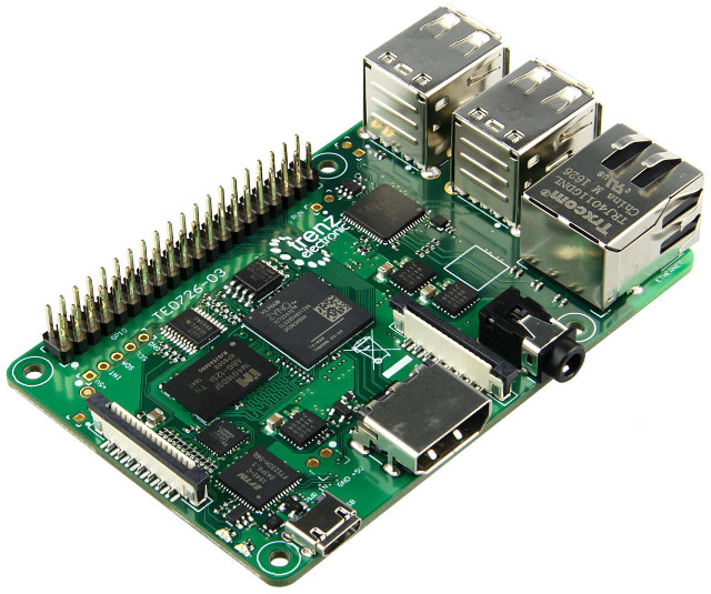
Earlier this year, I wrote about Trenz Electronic’s Xilinx Zynq Ultrascale+ system-on-module, but I’ve just found out I missed another interesting product
Source: Meet Zynqberry, a Xilinx Zynq FPGA Board with Raspberry Pi 2/3 Form Factor – CNX Software
Orbit/Pan Settings in Fusion 360
Fusion 360
- Zoom: roll the middle mouse button or Ctrl + Shift + middle mouse button
- Pan: middle mouse button
- Orbit: Shift + middle mouse button
Alias
- Zoom: Shift + Alt + right mouse button
- Pan: Shift + Alt + middle mouse button
- Orbit: Shift + Alt + left mouse button
Inventor (Windows only)
- Zoom: F3 + left mouse button
- Pan: F2 + left mouse button
- Orbit: F4 + left mouse button
SolidWorks
- Zoom: Shift + roll middle mouse button
- Pan: Ctrl + middle mouse button (Windows) or Command + middle mouse button (Mac)
- Orbit: Middle mouse button
Tinkercad
- Zoom: roll the middle mouse button or Ctrl + Shift + middle mouse button
- Pan: middle mouse button
- Orbit: right mouse button
Source: Tech Tip: How to Quickly Customize Orbit/Pan Settings in Fusion 360 – Fusion 360 Blog
How to Install Windows 11 Home With a Local Account – ExtremeTech
When you see the “Let’s connect you to a network” screen, hit Shift-F10, type “taskmgr” in the command prompt window, and kill the process called “Network connection flow.” According to the video, this will allow the OS to install normally after you insert a user login and password. You can also kill the application directly from the command line if you like, using the command “taskkill /F /IM oobenetworkconnectionflow.exe”
Source: How to Install Windows 11 Home With a Local Account – ExtremeTech