There are many ways to work around this problem, here are 2 simple ones, with their pros and cons:
Using a simple “delay()” function.
Using the “millis” function.
Using a simple “Delay()” Function
The way this works is when you start pressing the switch the first time the Arduino detects the desired state (LOW in this case) the delay() is started and waits between 50 and 200 milliseconds, this pauses the entire code on the Arduino until the delay is expired.
The reasoning is that the delay will be long enough to not let the Arduino read the bouncing and only register one switch press.
This method works fairly well but there are pros and cons:
Cons:
The delay() function is a ‘blocking’ function, freezing the execution of the Arduino code, so that when the delay is started nothing else can be done, such as reading a sensor or displaying values on an LCD, until the delay is expired.
It can’t be used inside Interrupts.
Pros:
Requires less coding than the millis() function and doesn’t need variables.
Easy to use and adequate for simple projects.
Using the “millis()” Function
The millis() function, when called, returns a time value (in milliseconds) that represent the time passed since the Arduino was powered up.
This timer is started automatically at power up without the need of any coding, so you can just call the function “millis()” to get the current value.
So by using some variables we can know the amount of time passed and use this instead of the delay() function.
The big advantage is that the millis() function is also a “non-blocking function” which means that the Arduino is not paused or frozen, so you can do other things unlike the delay() function which pauses the code completely.
Pros and cons:
Cons:
The millis() function requires a bit more coding since it requires variables compare to know how much time as passed.
The millis() timer will overflow (reset to zero) after approximately 49 days, no really a problem in most cases but something to keep in mind depending on how you use it.
Pros:
Since it doesn’t block or stops the code, you can do other things like check sensors or update display.
Can be used inside interrupts unlike the delay() function.
Useful for accurate timing of actions inside projects.
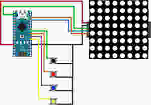
CONNECTIONS
In this tutorial we will be connecting 4 tact switches.
The black one will demonstrate switch bouncing.
The red and blue will show the delay() and millis() functions.
The yellow one will reset the LED Matrix counter.
THE CODE
All the switches are using the Arduino INPUT_PULLUP resistors to set their un-pressed state to HIGH.
We are also using some button state variables to make sure that when a switch is pressed and held down, the counter does not keep increasing.
Both the delay() and millis() function have a value of 100ms for debounce.
As always please watch the tutorial video for more information.
/* Arduino Switch Debounce Examples
Created by Yvan / https://Brainy-Bits.com
This code isin the public domain...
You can: copy it, use it, modify it, share it or just plain ignore it!
Thx!
*/// Needed for the LED Matrix#include <MD_Parola.h>#include <MD_MAX72xx.h>#include <SPI.h>#define HARDWARE_TYPEMD_MAX72XX::ICSTATION_HW/* PAROLA_HW, ///< Use the Parola style hardware modules.
GENERIC_HW, ///< Use 'generic' style hardware modules commonly available.
ICSTATION_HW, ///< Use ICStation style hardware module.
FC16_HW ///< Use FC-16 style hardware module.
*///Pins fromtheLEDMatrixtotheArduino#define MAX_DEVICES1#define CLK_PIN13#define DATA_PIN11#define CS_PIN10//Switches pins connected to Arduino#define switchpinBlack 6#define switchpinRed 5#define switchpinBlue 4#define switchpinYellow 3// Variable used for millis debounce
long TimeOfLastDebounce =0;// holds the last time the switch was pressed
long DelayofDebounce =100;// amount of time that needs to be experied between presses// Variable used to save the state of the switches// Needed so the counter only goes +1 for each keypress
int BlackButtonState =0;
int RedButtonState =0;
int BlueButtonState =0;// Variable to hold the value of the counter
int displaycounter=0;// Hardware SPI connection
MD_Parola P=MD_Parola(HARDWARE_TYPE,CS_PIN,MAX_DEVICES);voidsetup(void){P.begin();P.setTextAlignment(PA_CENTER);//All switches use the Arduino input pullup resistorspinMode(switchpinBlack,INPUT_PULLUP);pinMode(switchpinRed,INPUT_PULLUP);pinMode(switchpinYellow,INPUT_PULLUP);pinMode(switchpinBlue,INPUT_PULLUP);}voidloop(void){// Black Switch - No Debounceif(digitalRead(switchpinBlack)==LOW&& BlackButtonState ==0){
BlackButtonState=1;
displaycounter++;P.print(displaycounter);}else{if(BlackButtonState ==1&&digitalRead(switchpinBlack)==HIGH){
BlackButtonState=0;}}// Red Switch - Debounce using a delay() commandif(digitalRead(switchpinRed)==LOW&& RedButtonState ==0){delay(100);// The higher the Delay the less chance of bouncing
RedButtonState=1;
displaycounter++;P.print(displaycounter);}else{if(RedButtonState ==1&&digitalRead(switchpinRed)==HIGH){
RedButtonState=0;}}// Blue Switch - Debounce using a 'millis' timerif(digitalRead(switchpinBlue)==LOW&& BlueButtonState ==0){// check if enough time has passed to consider it a switch pressif((millis()- TimeOfLastDebounce)> DelayofDebounce){
BlueButtonState=1;
displaycounter++;
TimeOfLastDebounce =millis();P.print(displaycounter);}}else{if(BlueButtonState ==1&&digitalRead(switchpinBlue)==HIGH){
BlueButtonState=0;}}// Yellow Switch - Reset Counterif(digitalRead(switchpinYellow)==LOW){
displaycounter=0;}}
Hello Guys! I hope you have learned all about Arduino in my previous guide. Before doing any project based on the Arduino board it is very important that you should know the pin configuration of the board. So in order to help you guys, in this blog, I will guide you over the Pin configuration of each Arduino Model. After going through this blog you can do any project of Arduino with ease.
You will learn pin configuration of the following models:
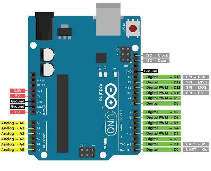
As we discussed we know that Arduino Uno is the most standard board available and probably the best choice for a beginner. We can directly connect the board to the computer via a USB Cable which performs the function of supplying the power as well as acting as a serial port.
Image Source: diyi0t.com
Vin: This is the input voltage pin of the Arduino board used to provide input supply from an external power source.
5V: This pin of the Arduino board is used as a regulated power supply voltage and it is used to give supply to the board as well as onboard components.
3.3V: This pin of the board is used to provide a supply of 3.3V which is generated from a voltage regulator on the board
GND: This pin of the board is used to ground the Arduino board.
Reset: This pin of the board is used to reset the microcontroller. It is used to Resets the microcontroller.
Analog Pins: The pins A0 to A5 are used as an analog input and it is in the range of 0-5V.
Digital Pins: The pins 0 to 13 are used as a digital input or output for the Arduino board.
Serial Pins: These pins are also known as a UART pin. It is used for communication between the Arduino board and a computer or other devices.The transmitter pin number 1 and receiver pin number 0 is used to transmit and receive the data resp.
External Interrupt Pins: This pin of the Arduino board is used to produce the External interrupt and it is done by pin numbers 2 and 3.
PWM Pins: This pins of the board is used to convert the digital signal into an analog by varying the width of the Pulse. The pin numbers 3,5,6,9,10 and 11 are used as a PWM pin.
SPI Pins: This is the Serial Peripheral Interface pin, it is used to maintain SPI communication with the help of the SPI library. SPI pins include:
SS: Pin number 10 is used as a Slave Select
MOSI: Pin number 11 is used as a Master Out Slave In
MISO: Pin number 12 is used as a Master In Slave Out
SCK: Pin number 13 is used as a Serial Clock
LED Pin: The board has an inbuilt LED using digital pin-13. The LED glows only when the digital pin becomes high.
AREF Pin: This is an analog reference pin of the Arduino board. It is used to provide a reference voltage from an external power supply.
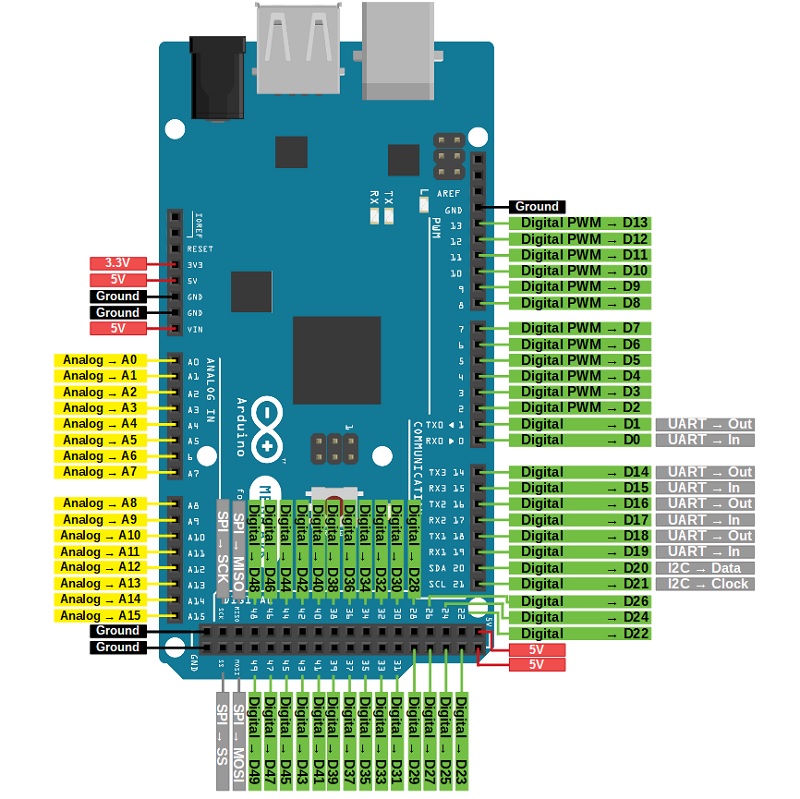
The most important thing about this board is that the board has more input-output pins so it is very beneficial for the Advanced Users or the people who want more pins for their projects.
Image Source: diyi0t.com
Vin: This is the input voltage pin of the Arduino board used to provide input supply from an external power source.
5V: This pin of the Arduino board is used as a regulated power supply voltage and it is used to give supply to the board as well as onboard components.
3.3V: This pin of the board is used to provide a supply of 3.3V which is generated from a voltage regulator on the board
GND: This pin of the board is used to ground the Arduino board.
Reset: This pin of the board is used to reset the microcontroller It is used to Resets the microcontroller.
Analog Pins: The pins A0 to A15 are used as an analog input and it is in the range of 0-5V. The analog pins on this board can be used as a digital Input or Output pins.
Serial pins: It is used for communication between the Arduino board and a computer or other devices.
The TXD and RXD are used to transmit & receive the serial data resp. It includes serial 0, Serial 1, serial 2, Serial 3 as follows:
Serial 0: It consists of Transmitter pin number 1 and receiver pin number 0
Serial 1: It consists of Transmitter pin number 18 and receiver pin number 19
serial 2: It consists of Transmitter pin number 16 and receiver pin number 17
Serial 3: It consists of Transmitter pin number 14 and receiver pin number 15
External Interrupts pins: This pin of the Arduino board is used to produce the External interrupt and it is done by the pin numbers 0,3,21,20,19,18.
I2C: This pin of the board is used for I2C communication.
Pin number 20 signifies Serial Data Line (SDA)and it is used for holding the data.
Pin number 21 signifies Serial Clock Line (SCL) and it is used for offering data synchronization among the devices.
SPI Pins: This is the Serial Peripheral Interface pin, it is used to maintainSPI communication with the help of the SPI library. SPI pins include:
MISO: Pin number 50 is used as a Master In Slave Out
MOSI: Pin number 51 is used as a Master Out Slave In
SCK: Pin number 52 is used as a Serial Clock
SS: Pin number 53 is used as a Slave Select
LED Pin: The board has an inbuilt LED using digital pin-13. The LED glows only when the digital pin becomes high.
AREF Pin: This is an analog reference pin of the Arduino board. It is used to provide a reference voltage from an external power supply.
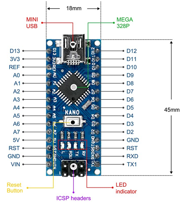
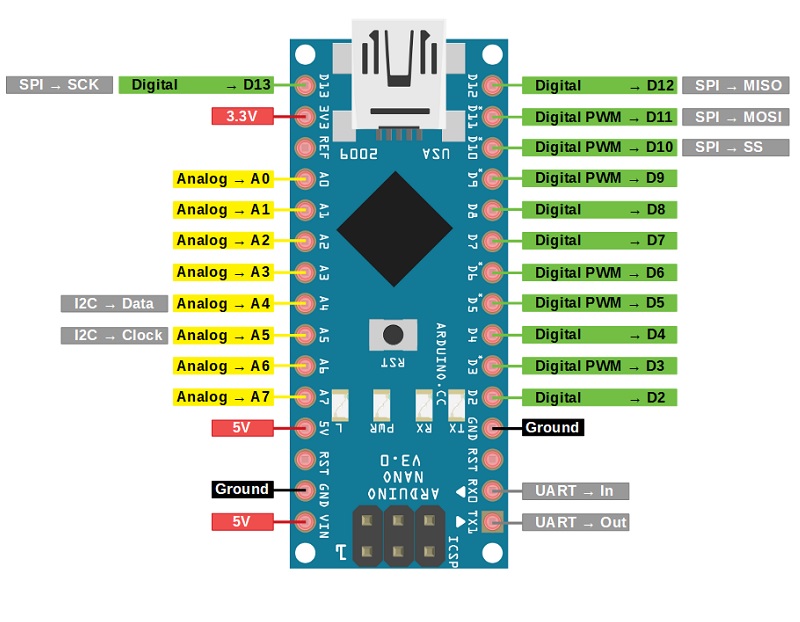
The Arduino Uno and nano are similar, but the only difference is that its size. The UNO size is 2 times the nano size, so the Arduino nano is more breadboard friendly. It is used for portable projects. The board has a mini USB cable slot.
Image Source: diyi0t.com
Vin: This is the input voltage pin of the Arduino board used to provide input supply from an external power source.
5V: This pin of the Arduino board is used as a regulated power supply voltage and it is used to give supply to the board as well as onboard components.
3.3V: This pin of the board is used to provide a supply of 3.3V which is generated from a voltage regulator on the board
GND: This pin of the board is used to ground the Arduino board.
Reset: This pin of the board is used to reset the microcontroller. It is used to Resets the microcontroller.
Analog Pins: The pins A0 to A7 are used as an analog input and it is in the range of 0-5V.
Digital Pins: The pins D0 to D13 are used as a digital input or output for the Arduino board.
Serial Pins: This pin is also known as a UART pin. It is used for communication between the Arduino board and a computer or other devices. The transmitter pin number 1 and receiver pin number 2 is used to transmit and receive the data resp.
External Interrupt Pins: This pin of the Arduino board is used to produce the External interrupt and it is done by pin numbers 2 and 3.
PWM Pins: This pins of the board is used to convert the digital signal into an analog by varying the width of the Pulse. The pin numbers 3,5,6,9,10 and 11 are used as a PWM pin.
SPI Pins: This is the Serial Peripheral Interface pin, it is used to maintainSPI communication with the help of the SPI library. SPI pins include:
SS: Pin number 10 is used as a Slave Select
MOSI: Pin number 11 is used as a Master Out Slave In
MISO: Pin number 12 is used as a Master In Slave Out
SCK: Pin number 13 is used as a Serial Clock
I2C: This pin of the board is used for I2C communication.
Pin A4 signifies Serial Data Line (SDA)and it is used for holding the data.
Pin A5 signifies Serial Clock Line (SCL) and it is used for offering data synchronization among the devices.
LED Pin: The board has an inbuilt LED using digital pin-13. The LED glows only when the digital pin becomes high.
AREF Pin: This is an analog reference pin of the Arduino board. It is used to provide a reference voltage from an external power supply.
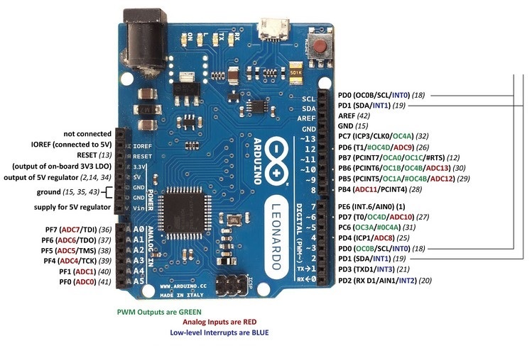
The Arduino Leonardo has more number of digital input/ output and analog input pins. The Arduino Leonardo can be powered via the micro USB connection or with an external power supply.
Image Source: electroschematics.com
Vin: This is the input voltage pin of the Arduino board used to provide input supply from an external power source.
5V: This pin of the Arduino board is used as a regulated power supply voltage and it is used to give supply to the board as well as onboard components.
3.3V: This pin of the board is used to provide a supply of 3.3V which is generated from a voltage regulator on the board
GND: This pin of the board is used to ground the Arduino board.
Reset: This pin of the board is used to reset the microcontroller. It is used to Resets the microcontroller.
Analog Pins: The pins A0 to A11 are used as an analog input and it is in the range of 0-5V.
Digital Pins: The pins 4, 6, 8, 9, 10, and 12 are used as a digital input or output for the Arduino board.
Serial Pins: This pin is also known as a UART pin. It is used for communication between the Arduino board and a computer or other devices. The transmitter pin number 1 and receiver pin number 0 is used to transmit and receive the data resp.
External Interrupt Pins: This pin of the Arduino board is used to produce the External interrupt and it is done by pin numbers 2 and 3.
I2C: This pin of the board is used for I2C communication.
Pin number 2 signifies Serial Data Line (SDA)and it is used for holding the data.
Pin number 3 signifies Serial Clock Line (SCL) and it is used for offering data synchronization among the devices.
LED Pin: The board has an inbuilt LED using digital pin-13. The LED glows only when the digital pin becomes high.
AREF Pin: This is an analog reference pin of the Arduino board. It is used to provide a reference voltage from an external power supply.
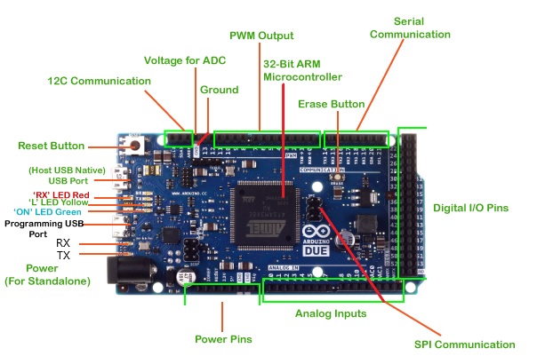
Arduino Due is more preferable when there are many peripherals that need to connect the board. This board has many numbers of PWM and ADC outputs so it can be more beneficial to use the Due board where you will need more PWM and ADC pins. It is the perfect board for powerful larger scale Arduino projects like designing complex systems like CNC or 3D printer.
Image Source: javatpoint.com
Vin: This is the input voltage pin of the Arduino board used to provide input supply from an external power source.
5V: This pin of the Arduino board is used as a regulated power supply voltage and it is used to give supply to the board as well as onboard components.
3.3V: This pin of the board is used to provide a supply of 3.3V which is generated from a voltage regulator on the board
IOREF: It stands for Input-Output voltage REFerence. It allows the shields to check the operating voltage of the board.
GND: This pin of the board is used to ground the Arduino board.
Reset: This pin of the board is used to reset the microcontroller. It is used to Resets the microcontroller.
Analog Pins: The pins A0 to A11 are used as an analog input and it is in the range of 0-5V.
Digital Pins: The pins 0 to 53 are used as a digital input or output for the Arduino board.
PWM Pins: This pins of the board is used to convert the digital signal into an analog by varying the width of the Pulse. The pin numbers 2 to 13 are used as PWM pins.
SPI Pins: This pin is also known as a UART pin. It is used for communication between the Arduino board and a computer or other devices. The transmitter pin and receiver pin are used to transmit and receive the data resp.
I2C Communication: This pin of the board is used for I2C communication.
Serial Data Line (SDA): It is used for holding the data.
Serial Clock Line (SCL): It is used for offering data synchronization among the devices.
Voltage for ADC: This pin of the Arduino board is used to map the voltage value to the integer value. The voltage from 0 to 5 is mapped into the integer value from 0 to 1023.
Erase Button: This pin of the board is used to erase the Flash Memory of the microcontroller. To erase, on the power of the board press and hold the Erase button for a few seconds.
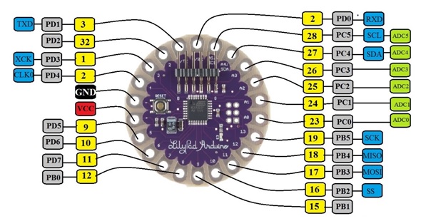
Arduino Lilypad is very unique in its shape and applications among the other Arduino boards. This Arduino Lilypad is based on the circular PCB with the wide holes at the corner and is optimized for the e-textiles and wearable projects. The Arduino Lilypad does not have built-in USB to UART converter as it is present in other Arduino modes.
Image Source: projectiot123.com
VCC: This pin of the Arduino board is connected to +5V or +3.3V for providing supply to the board
GND: This pin of the board is used to ground the Arduino board.
Reset: This pin of the board is used to reset the microcontroller. It is used to Resets the microcontroller.
Analog Pins: The pins A0 to A5 are used as an analog input and it is in the range of 0-5V.
Digital Pins: The board contains 14 digital pins that can be used as an input or output.
Serial Pins: This pin is also known as a UART pin. It is used for communication between the Arduino board and a computer or other devices. The transmitter and are used to transmit and receive the data resp.
PWM: These pins of the board are used to convert the digital signal into an analog by varying the width of the Pulse. The pin numbers 9, 10, 15, 16, and 17 are used as PWM pins.
SPI Pins: This is the Serial Peripheral Interface pin, it is used to maintainSPI communication with the help of the SPI library. SPI pins include:
SS: Pin number 16 is used as a Slave Select
MOSI: Pin number 17 is used as a Master Out Slave In
MISO: Pin number 18 is used as a Master In Slave Out
SCK: Pin number 19 is used as a Serial Clock
I2C Communication: This pin of the board is used for I2C communication.
Serial Data Line (SDA): It is used for holding the data.
Serial Clock Line (SCL): It is used for offering data synchronization among the devices.
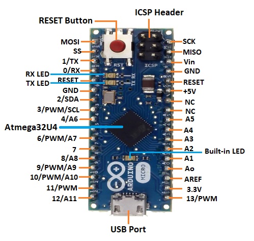
Arduino Micro is the smallest board in the Arduino Community. The Arduino Micro has more number of analog input pins than the UNO board. It is essentially a shrunk-down version of the Arduino Leonardo
Image Source: javatpoint.com
Vin: This is the input voltage pin of the Arduino board used to provide input supply from an external power source.
5V: This pin of the Arduino board is used as a regulated power supply voltage and it is used to give supply to the board as well as onboard components.
3.3V: This pin of the board is used to provide a supply of 3.3V which is generated from a voltage regulator on the board
GND: This pin of the board is used to ground the Arduino board.
Reset: This pin of the board is used to reset the microcontroller. It is used to Resets the microcontroller.
Analog Pins: The pins A0 to A11 are used as an analog input and it is in the range of 0-5V.
Digital Pins: The pins 4, 6, 8, 9, 10, and 12 are used as a digital input or output for the Arduino board.
External Interrupt Pins: This pin of the Arduino board is used to produce the External interrupt and it is done by pin number 0, 1, 2, and 3.
PWM Pins: This pins of the board is used to convert the digital signal into an analog by varying the width of the Pulse. The pin numbers 3, 5, 6, 9, 10, 11, and 13 are used as PWM pins.
Serial Pins: This pin is also known as a UART pin. It is used for communication between the Arduino board and a computer or other devices. The transmitter pin number 1 and receiver pin number 0 is used to transmit and receive the data resp.
I2C: This pin of the board is used for I2C communication.
Pin number 2 signifies Serial Data Line (SDA)and it is used for holding the data.
Pin number 3 signifies Serial Clock Line (SCL) and it is used for offering data synchronization among the devices.
SPI Pins: This is the Serial Peripheral Interface pin, it is used to maintainSPI communication with the help of the SPI library. SPI pins include:
SS: It is used as a Slave Select
MOSI: It is used as a Master Out Slave In
MISO: It is used as a Master In Slave Out
SCK: It is used as a Serial Clock
LED Pin: The board has an inbuilt LED using digital pin-13. The LED glows only when the digital pin becomes high.
AREF Pin: This is an analog reference pin of the Arduino board. It is used to provide a reference voltage from an external power supply.
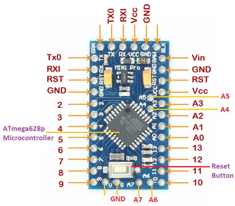
The Arduino Pro mini has the new pin called the RAW pin. The RAW PIN is the input to the on-board regulator. You can connect up to 12V to the RAW pin and VCC will remain at a constant voltage. This Arduino board is preferred by advanced users for greater flexibility and small size.
Image Source: javatpoint.com
Vin: This is the input voltage pin of the Arduino board used to provide input supply from an external power source.
VCC: This pin of the Arduino board is connected to +5V or +3.3V for providing supply to the board
GND: This pin of the board is used to ground the Arduino board.
Reset: This pin of the board is used to reset the microcontroller. It is used to Resets the microcontroller.
Analog Pins: The pins A0 to A7 are used as an analog input and it is in the range of 0-5V.
Digital Pins: The pins 2 to 13 are used as a digital input or output for the Arduino board.
External Interrupt Pins: This pin of the Arduino board is used to produce the External interrupt and it is done by the pin number 4 and 5
PWM Pins: This pin of the board is used to convert the digital signal into an analog by varying the width of the Pulse. The pin numbers 3, 5, 6,9,10, and 12 are used as a PWM pin.
Analog Comparator: Pin number 6 -AIN0 and pin number 7- AIN1 are connected to the internal comparator.
SPI Pins: This is the Serial Peripheral Interface pin, it is used to maintainSPI communication with the help of the SPI library. SPI pins include:
SS: Pin number 10 is used as a Slave Select
MISO: Pin number 11 is used as a Master In Slave Out
MOSI: Pin number 12 is used as a Master Out Slave In
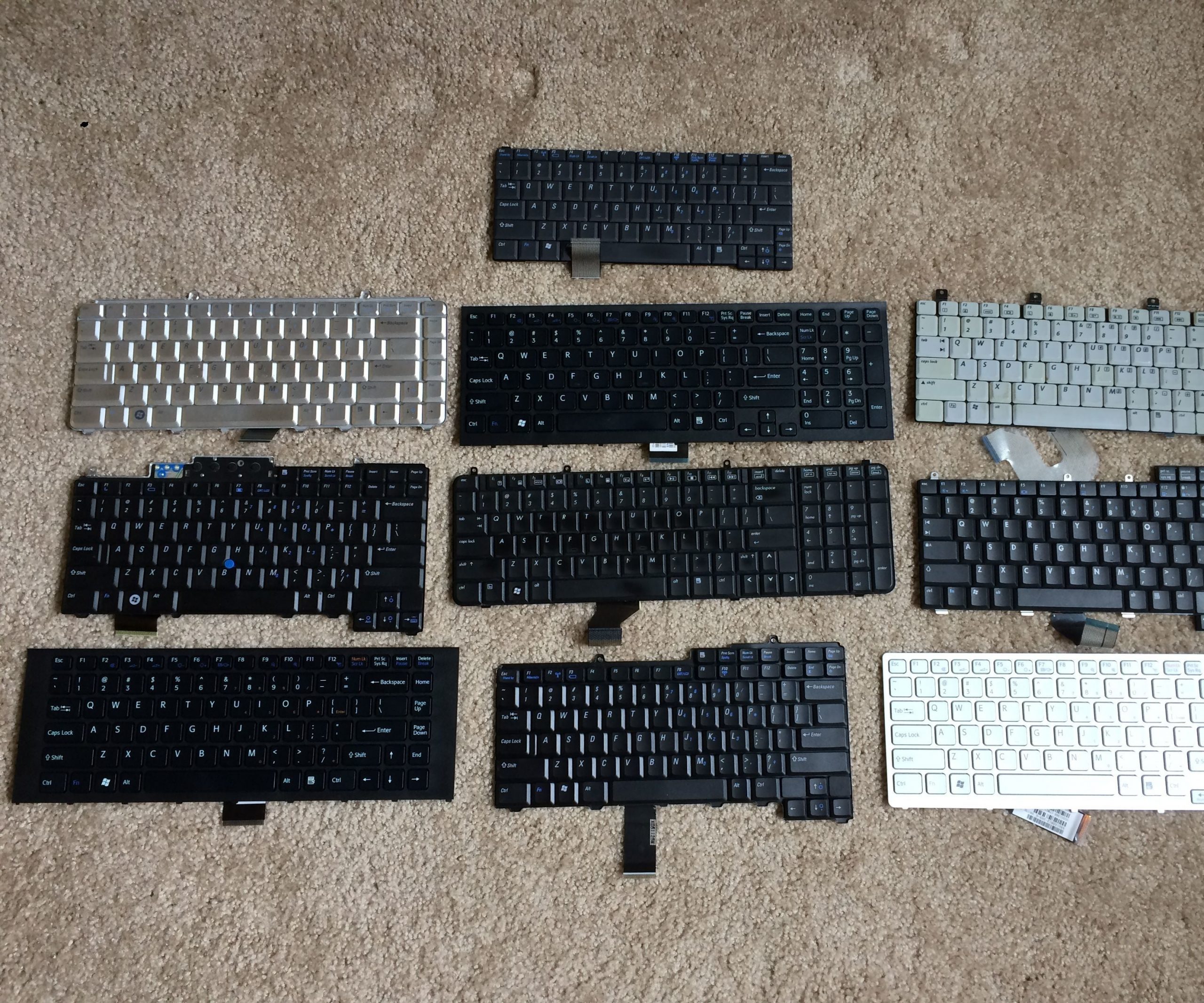
How to Make a USB Laptop Keyboard Controller : This Instructable will provide a step by step procedure for building a USB laptop keyboard and touchpad controller. I created this guide and video to hopefully make it easier for people to re-purpose an old laptop. A typical laptop keyboard relies o…
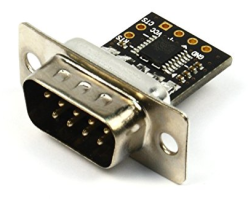
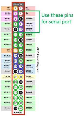
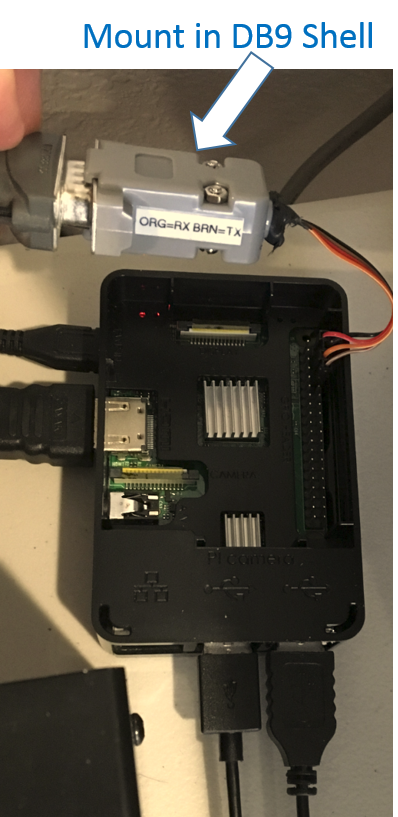
An RS232-to-TTL converter converts RS232 voltage levels to TTL levels that can be used by the Pi (and vice versa). I use NulSom’s Ultra Compact RS232 to TTL Converter with Male DB9. This converter fits within a DB9 back shell.
The converter has solder terminals that I connected to female header adapters, and connected to pins 4, 6, 8, and 10 on the Pi.
The setup is more compact compared to using a USB adapter.
In the Pi, the serial port might need to be enabled in the configuration settings.
My serial port shows up in the /dev folder as ttyS0.
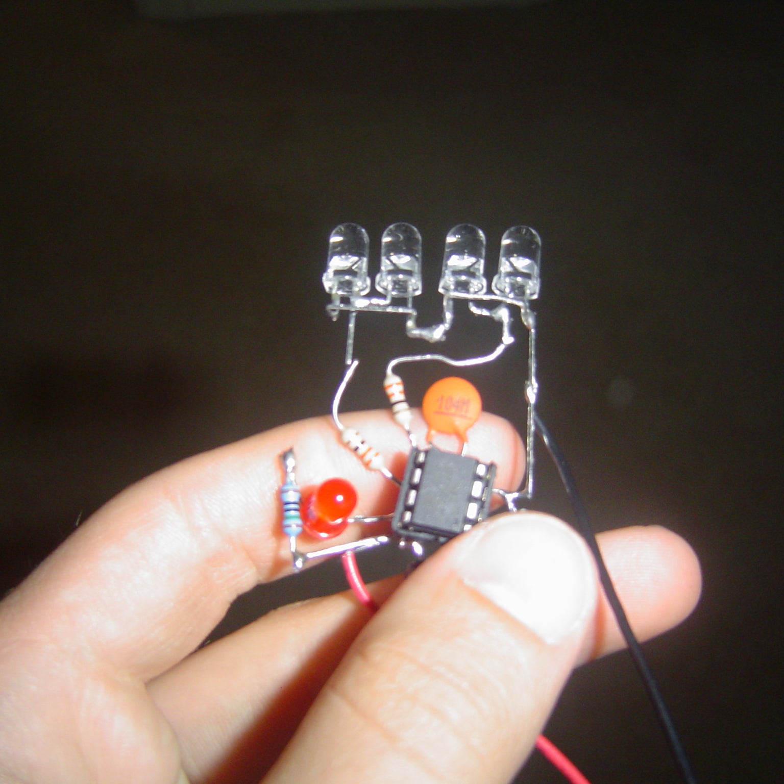
$3.50 DIY TV-B-Gone Micro: I previously made a slideshow on my DIY TV-B-Gone, and many people requested I make an Instructable. So, the first in a series of DIY TV-B-Gone clones, is the TV-B-Gone Micro! Technically, because TV-B-Gone is a brand name, this is a “TV-B-Gone clo…