All posts by smarc
Recover From Grub Failure – Proxmox VE
General advice
During to the upgrade from 3.x to 4.x, I found myself without a working grub and unable to boot. Monitor shows:
grub rescue >
You can use Proxmox installation ISO in verison 5.4 or newer, and select debug mode. On the second prompt you’ll have the full Linux tools, including LVM, ZFS, …, available. If you exit that prompt you will come to the installation screens, simply hit abort there.
Alternatively, one can use a 64 bit version of Ubuntu or Debian Rescue CD.
Boot Proxmox VE in debug mode, or the Ubuntu/Debian off the ISO. We do not want to install Ubuntu/Debian, just run it live off the ISO/DVD.
First We need to activate LVM and mount the the root partition that is inside the LVM container.
sudo vgscansudo vgchange -ay
Mount all the filesystems that are already there so we can upgrade/install grub. Your paths may vary depending on your drive configuration.
sudo mkdir /media/RESCUEsudo mount /dev/pve/root /media/RESCUE/sudo mount /dev/sda1 /media/RESCUE/bootsudo mount -t proc proc /media/RESCUE/procsudo mount -t sysfs sys /media/RESCUE/syssudo mount -o bind /dev /media/RESCUE/devsudo mount -o bind /run /media/RESCUE/run
Chroot into your proxmox install.
chroot /media/RESCUE
Then update grub and install it.
update-grubgrub-install /dev/sda
If there are no error messages, you should be able to reboot now.
Credit: https://www.nerdoncoffee.com/operating-systems/re-install-grub-on-proxmox/
Recovering from grub “disk not found” error when booting from LVM
This section applies to the following setups:
- PVE 7.4 (or earlier) hosts with their boot disk on LVM
- PVE 8 hosts that have their boot disk on LVM, boot in UEFI mode and were upgraded from PVE 7
In these setups, the host might end up in a state in which grub fails to boot and prints an error disk `lvmid/<vg uuid>/<lv uuid>` not found. An example (of course, the UUIDs vary):
Welcome to GRUB!

error: disk `lvmid/p3y5O2-jync-R2Ao-Gtlj-It3j-FZXE-ipEDYG/bApewq-qSRB-zYqT-mzvP-pGiV-VQaf-di4Rcz` not found.
grub rescue>
This error “disk `…` not found” error is originally caused by a grub bug. LVM metadata is stored on-disk in a ring buffer, so occasionally the current metadata will wrap around the end of the ring buffer. However, if there is a wraparound in the ring buffer, grub fails to parse the metadata and fails to boot with the above error.
The recommended steps differ between the PVE 7.4 and PVE 8.
PVE 7.x
This subsection applies to PVE 7.4 (or earlier) hosts with their boot disk on LVM.
PVE 7.4 ships grub 2.06-3~deb11u5 which is affected by the bug (though earlier versions may also be affected). This was also reported multiple times in the forum already, see here and here.
Temporary Workaround
In order to temporarily work around this bug and get the host to a bootable state again, it is sufficient to trigger an LVM metadata update. The updated metadata will reside in one contiguous section of the metadata ring buffer, so no wraparound occurs anymore. grub will then be able to parse the metadata correctly and boot again.
One simple way to trigger an LVM metadata update is to create a small logical volume:
- Boot from a live USB/CD/DVD with LVM support, e.g. grml
- Run
vgscan - Create a 4MB logical volume named
grubtempin thepvevolume group:lvcreate -L 4M pve -n grubtemp - Reboot. PVE should boot normally again.
- You can now remove the
grubtempvolume:lvremove pve/grubtemp
Note that there are many other options for triggering a metadata update, e.g. using lvchange to extend an existing logical volume or add a tag to an existing logical volume.
The workaround is only temporary: If the host is (re)booted at a time when there is again a wraparound in the metadata ring buffer, grub will fail to boot again.
On a running PVE system, you can check whether there is a wraparound in the metadata ring buffer using the following command:
vgscan -vvv 2>&1 | grep "Reading metadata"
If the output lines end with (+0), there is no wraparound. If they end with (+N) for any other number N, there is a wraparound and the grub will most likely fail to boot after a reboot.
Permanent Fix
The only permanent fix for PVE 7.x is:
- Apply the temporary workaround to be able to boot PVE again
- Upgrade to PVE 8 by following the upgrade guide.
PVE 8
This subsection applies to PVE 8 hosts that have their boot disk on LVM, boot in UEFI mode and were upgraded from PVE 7.
PVE 8 ships grub 2.06-13 in which the grub bug is fixed. However, on hosts that boot in UEFI mode and were upgraded from PVE 7, it can happen that the updated grub 2.06-13 EFI binary is not installed to the EFI system partition (ESP) at /boot/efi/EFI/proxmox/grubx64.efi. As a result, when booting in UEFI mode, the host still runs the older grub 2.06-3~deb11u5 binary that is affected by the grub bug. To find out whether this is the case, check its mtime using ls -l /boot/efi/EFI/proxmox/grubx64.efi. If it is older than the time of the upgrade from PVE 7 to 8, the host still runs the older grub binary when booting in UEFI mode.
Temporary Workaround
The temporary workaround for PVE 8 to get the host in a bootable state is the same as for PVE 7.x (see above).
Permanent Fix
The issue can be fixed permanently on PVE 8 by installing the correct grub metapackage for UEFI and choosing the correct UEFI boot entry.
First, apply the temporary workaround to be able to boot into PVE 8 again. When booted into PVE 8, run the following command. It checks if the host is indeed booted in UEFI mode, and if yes, installs the correct grub metapackage for UEFI:
[ -d /sys/firmware/efi ] && apt install grub-efi-amd64
This will remove the grub-pc package, and update the binary on the ESP. You can verify that the mtime of /boot/efi/EFI/proxmox/grubx64.efi was updated.
Note that this will not update the default EFI binary at /boot/efi/EFI/BOOT/BOOTx64.EFI, which might still be the grub binary that is affected by the bug. Consequently, make sure that you select the proxmox boot entry when booting in UEFI mode. If needed, you can adjust the boot order directly in the UEFI firmware or using the efibootmgr tool (see its manpage).
Windows create local user
To create a local account
Search for CMD, then run in administrator mode and enter the following command
net user USERNAME PASSWORD /addnet localgroup administrators USERNAME /addUSERNAME PASSWORD can be replaced with the account name and PASSWORD you want, and password can be omitted if no password is needed.
No Quarters Arcade – Frank’s Pinball Battery Boards, Tech Tips and Blog
ipapi-is/ip_to_asn: Find rich ASN information for each IP address. The output includes IP suffixes, AS type, AS country, AS organisation and so on…
Ninite – Install or Update Multiple Apps at Once
SevenSeg/extras/SevenSeg.pdf at master · sigvaldm/SevenSeg
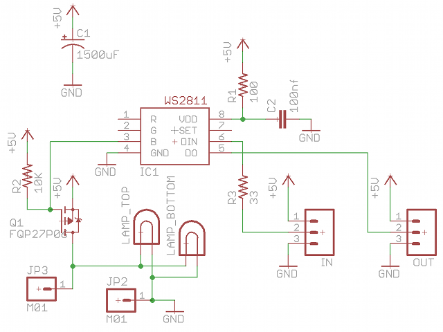
Individually Addressable Incandescent Lamps
FAKRA Connector Types and Codes
FAKRA Connector Types
FAKRA connectors are specialized RF (Radio Frequency) connectors developed primarily for automotive applications, ensuring secure, high-frequency signal transmission.
FAKRA (Fachkreis Automobil) connectors are modified SMB (SubMiniature version B) connectors housed in a plastic shell that adds mechanical stability, color coding, and keying. These enhancements ensure proper mating, vibration resistance, and safety in automotive apps (GPS, LTE, AM/FM, satellite radio and Bluetooth among others).
Key Features of FAKRA Connectors
- Standardized Color Coding: Each FAKRA connector type is color-coded to prevent mismatches during installation.
- Durability: Built to withstand harsh conditions, FAKRA cables operate effectively in temperatures ranging from -40°C to 105°C.
- High-Frequency Performance: Capable of handling RF frequencies up to 6.0 GHz, making them suitable for various wireless technologies.
- Secure Locking Mechanism: Features a primary and secondary locking system to ensure stable and reliable connections.
- Versatility: Supports both single and double configurations, enhancing utility across different devices.
- FAKRA connector standard
Is a global standard for automotive connectors. The standard specifies a plastic housing and 14 mechanical, color-coded elements to prevent incorrect mating. Is standardized under USCAR and ISO 20860. The FAKRA standard specifications are:
| Impedance | 50 Ohm |
| Frequency Range | DC – 6 GHz |
| Voltage Rating | 335 Volts RMS Continuous |
| Dielectric Withstanding Voltage | 800 VRMS Max |
| VSWR (Return Loss) (3 – 6 GHz) | 1.6 (-13dB) Max |
| Insulation Resistance | 100 MΩ Min |
| Insertion Loss (3 – 6 GHz) | 0.45 dB |
| Power Handling | 95 W Max @ 1 GHz @ 25ºC |
| Mating Cycles | 100 Min |
| Coupling Mechanism | Push-On |
| Temperature Range | −40°C to +105°C |
FAKRA Connector Types (Coding)
There are primary FAKRA codes, each associated with a specific color and mechanical key to prevent misconnection. Here’s a summary:
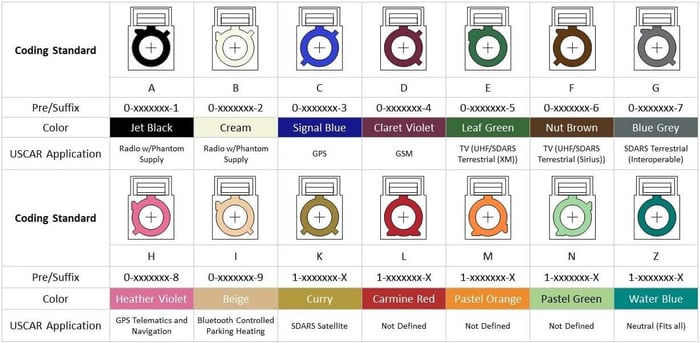
Note: FAKRA Water Blue code is universal, meaning it can mate with any other type but doesn’t prevent mismating—used mostly in lab settings or generic applications.
FAKRA Type F connectors are color-coded brown, corresponding to RAL 8011. This standard is consistently documented across multiple reputable references:
- The Rosenberger FAKRA Number Code chart lists Type F as brown (RAL 8011). Rosenberger Group
- The Mouser Electronics FAKRA Number Code document also specifies Type F with a brown color code. Mouser Electronics+1Rosenberger Group+1
- The element14 Community’s comprehensive guide to FAKRA connectors confirms the brown color coding for Type F. element14 Community+1element14 Community+1
The brown color coding for Type F connectors is standardized under the USCAR and ISO 20860 specifications, ensuring consistency across manufacturers and applications. This coding helps prevent mismating and simplifies installation and maintenance in automotive RF and communication systems.
Gender and Mating
- FAKRA Plug (Male): Center pin, usually goes on the cable side.
- FAKRA Jack (Female): Center sleeve, usually on the device/housing.
Variants and Mounting Styles
FAKRA connectors come in various configurations, including:
- Straight or right-angle
- PCB mount or panel mount
- Cable mount (crimp or solder)
- Sealed or unsealed
FAKRA connector standard
The mechanical keying system in FAKRA connectors is a crucial feature designed to prevent mismating, ensure correct signal routing, and maintain safety—especially in complex automotive and RF environments where multiple similar-looking connectors are used.
Here’s a breakdown of how the mechanical keying in FAKRA connectors works:
1. Unique Plastic Housing with Keying Features
Each FAKRA connector is built around a standard SMB RF interface, but it’s enclosed in a rectangular plastic housing that provides:
- Color coding (visual identification)
- Mechanical keying (physical differentiation)
The keying consists of protrusions (ridges) and notches (slots) on the outer housing that are unique for each FAKRA code (A through Z). These physical features prevent connectors with different key codes from mating.
2. Mating Compatibility is Code-Specific
- A FAKRA Plug (male) with code A (violet) can only mate with a FAKRA Jack (female) that has the same mechanical key and color (code A).
- Even if two connectors look similar in size and shape, if their keys don’t match, they won’t physically connect.
- This design eliminates human error during installation, particularly important in automotive manufacturing lines where speed and accuracy are critical.
3. FAKRA Z – The Universal Option
The exception is FAKRA Z (water blue), which has no keying. It can physically mate with any other FAKRA type. It’s typically used:
- In test environments
- For lab prototypes
- When a universal connection is acceptable
But Z-type connections sacrifice the safety of keying, so they’re not used in critical automotive systems.
4. Application Examples
- GPS (Code A, violet): Only connects to GPS modules
- Camera (Code H, orange): Only connects to camera inputs
- FM Radio (Code B, blue): Only plugs into FM antenna ports
This ensures that a GPS antenna isn’t accidentally plugged into an FM radio port, avoiding signal mismatches or system failure.
5. Assembly and Locking
Once aligned correctly (keyed ridges match), the connectors snap together with an audible “click”, indicating a secure connection. Most housings also include a locking tab or retention clip for vibration resistance.
Data Alliance offers a variety of FAKRA connectors and cables designed for RF applications, particularly in automotive, IoT, and wireless communication systems. Here’s an overview of the types available:
Types of FAKRA Connectors Available at Data Alliance
- FAKRA-Female to SMA-Female Cables
These cables connect FAKRA female connectors to SMA female connectors, facilitating integration between automotive-grade RF systems and standard SMA-equipped devices. - FAKRA-Female to RP-SMA-Female Cables
Designed to connect FAKRA female connectors to RP-SMA female connectors, these cables are suitable for applications requiring reverse polarity SMA interfaces. - FAKRA Type F Male to Female Extension Cable – 20 inches (52cm), LMR-100 Equivalent.
Data Alliance provides these cables in multiple lengths (e.g., 2-inch, 4-inch, 6-inch, 24-inch) to accommodate different installation requirements.
Applications
- Automotive: Used in GPS systems, in-vehicle entertainment, keyless entry, parking sensors, and more.
- IoT Devices: Ideal for devices requiring stable wireless connections in varying environmental conditions.
- Telecommunications: Enhances signal reliability in various telecommunication equipment.
For more detailed information and to explore their product offerings, you can visit Data Alliance’s FAKRA Cables & Adapters page.
Conclusions
For industries leaning heavily on IoT and automotive advancements, FAKRA connectors and cables seem to be the bridge leading to a more connected and efficient future.
The dynamic technological landscape has pushed the boundaries of wireless communication, resulting in more stringent requirements for connectors and cables. A remarkable entrant in this domain is FAKRA (Fachkreis Automobil), a German acronym that translates to “expert group for automotive.” These cables have made a significant impact in the domain of wireless technologies, particularly in automobile and IoT applications.
Source: FAKRA Connector Types and Codes
FAKRA Series Part 2: Connector Part Number and Generations Explained | Amphenol RF
FAKRA Part Numbers Explained:
To search for FAKRA parts for your next project follow this link. When you get there, you may find yourself a bit confused at which part number you should select! The key codes and colors were discussed in Part 1 of this series and here we will break down the part number scheme to help you better choose your parts:
Let’s go through an Example P/N:
This part is a Gen 2, Single position, North tab location, D key code, Straight Plug, Cable connector for Cable Group 01 (see below), with a standard contact, in-line connector. How can you tell the difference between Gen 2 vs. Gen 2.5? That will be discussed in the Generations section of this post!
Special Codes:
One more Example P/N:
This a Gen 1, Single position, North tab location, A key code, Straight Plug, PCB, vertical mount connector.
FAKRA Generations Explained:
Generation 1: FAKRA Generation 1.0 utilizes a modified metal SMB connector embedded within a plastic housing unit for ease of identification and assembly. These plastic housings are designed with visually and mechanically coded and keyed tooling to eliminate assembly errors. Our standard FAKRA connectors are designed to perform up to 4 GHz and meet the electrical, mechanical and environmental standards of the automotive industry. Generation 1.0 typically features five separate component parts. Gen 1 FAKRA is a die cast or machined body with machined contact. Can assemble with hand tools.
Generation 2: FAKRA Generation 2.0 offers reduced installation costs for our customers via a pre-assembled housing unit. This pre-assembled housing eliminates two loose components and their associated assembly and handling costs. Due to this component reduction, Generation 2.0 features three separate components to install versus Generation 1.0’s five separate components. Summary: Gen 2 FAKRA is a die cast or machined body with machined contact. Gen 2 is an evolution of Gen 1. Can assemble with hand tools.
Generation 2.5: FAKRA Generation 2.5 offers the same pre-assembled housing units and design improvements as Generation 2.0, but center contacts are provided on a tape and reel for automated distribution and placement. Summary: Gen 2.5 FAKRA is a die cast body and has a stamped contact, a significant modification from Gen 1 and 2. The contacts are sold separately on tape and reel. This Generation requires automated tooling to assemble.
Generation 3: Generation 3 currently only exist for jacks (not applicable for plugs). Gen 3 jacks incorporate the same construction features as the Gen 2.5 jacks. Additionally, the Gen 3 has been enhanced with a closed-entry interface and a protected outer contact, making the connector more robust than traditional SMB’s. The stamped and formed center contact continues to be supplied on a reel, allowing for semi-automated termination onto the cable. Summary: Gen 3 FAKRA is a die cast body and has a stamped contact, an evolution of Gen 2.5. The contacts are sold separately on tape and reel. This Generation requires automated tooling to assemble.
Generation 4: Gen 4 plugs and jacks are designed for fully automated termination by the user. Not only the center contacts but the connector bodies themselves are supplied strip-fed on tape and reel. This connector offering will be directed to the high volume users whose factory utilize high-speed automated cable assembly production. The connectors are stamped and formed construction. The FAKRA connector housings for Gen 4 are removable, permitting field replacement if necessary. Summary: Gen 4 FAKRA is fully stamped and formed – both body and contact! Huge leap forward from Gen 3. All components are sold separately on tape and reel. This Generation requires fully automated tooling to assemble.
Recommendations:
If you are interested in incorporating FAKRA connectors into your non-automotive application, Gen 1 or Gen 2 products are likely your best option. These can be terminated by normal hand tools and are shipped complete. If you are a high volume automotive supplier, a Gen 2.5, 3, or 4 product is going to be the ideal product for your application. These require special tooling and setups that are only typically found in very high volume applications.
As always, feel free to contact us with any questions you have!
Next in the series: Custom FAKRA capabilities, sealed FAKRA, FAKRA applications, and uses outside of automotive! Check out the latest FAKRA cutsheet for our Gen 3 product offering including the contacts on tape and reel.


Source: FAKRA Series Part 2: Connector Part Number and Generations Explained | Amphenol RF