Source: Online Tone Generator – Free, Simple and Easy to Use.
Monthly Archives: December 2020
wxPerl – Perl wtapper for the wxWidgets GUI toolkit

http://www.wxperl.it/
http://wiki.wxperl.it/
pp – Perl Packager – metacpan.org
A Beginner’s Guide to Compiling Perl Scripts – marcbilodeau.com
Marv Klotz’s Utilities
SOFTWARE FOR PEOPLE WHO BUILD THINGS!
Suricata inline versus legacy IPS mode | Netgate Forum
I will just add a little more detail to the explanation to highlight the differences between inline IPS mode and the legacy IDS/IPS hybrid mode.
In legacy mode, the pcap library is used to make a copy (clone if you will) of every packet as it comes in from the NIC on its way to the pf firewall engine. The original packet continues on to the pf firewall engine and is either passed or blocked depending on the current rules in the firewall. Meanwhile, the cloned packet is sent over to Suricata (or Snort if using that package) for inspection against the IDS/IPS rules. Should the cloned packet (or packets, since sometimes Suricata needs to see a group of packets before a decision can be made) be judged as “bad” by the Suricata engine, then a system call is made to insert the offending IP address from the packet into a special table in the pf firewall engine called snort2c. IP addresses in this special table are blocked. However, note that this decision making and subsequent insertion of the IP address into the snort2c table has happened well after the original packet (or packets if a group of packets was required to make a decision) has traversed the pf engine. So that original packet will have already gotten past the IPS mechanism. Packets that subsequently come through from the same IP address will now get blocked, though. Hence I use the term “hybrid IDS/IPS” because a true IPS would never leak a packet. A true IPS would hold up the original packet while it was being inspected, and then either pass it or drop it. Legacy mode does not hold up the original packet. It is allowed to continue on to the firewall while the cloned copy is used to make the decision for blocking future packets from the IP address.
With the new inline IPS mode, Suricata activates and uses the relatively new Netmap mechanism that was added to FreeBSD. Netmap is a way for applications to create a highspeed pipe between the NIC driver layer and the rest of the system. So packets coming and going on a given network interface must pass through the Netmap pipe. Suricata inline-mode controls the “door” in this pipe. Each packet stream coming from the NIC (or going to the NIC) is inspected by Suricata and a “pass” or “drop” decision is made. If a packet is dropped, it is never forwarded on to the pfSense kernel and thus never makes it to the pf engine. Since every single packet must traverse this Netmap pipe, there is no leakage. No copies of the packets are made for examination. Everything occurs with the original packet.
The downside of the new inline mode is that for now only some NIC drivers support working with the Netmap API mechanism. So while legacy mode is pretty much NIC card and driver agnostic (meaning it works with any hardware), the inline mode is highly dependent on your firewall having a NIC driver that supports Netmap. Another problem that currently exists is the Netmap pipe seems to break traffic shaping on the interface. I suspect this is a fixable problem, but no solution is in place yet.
So consider these two issues before choosing to use the inline IPS mode: (1) do I have a supported NIC and driver; and (2) can I do without traffic shaping on interfaces where I run Suricata?
Source: Suricata inline versus legacy IPS mode | Netgate Forum
Note:
Important Information About IPS Inline Mode Blocking
When using Inline IPS Mode blocking, you must manually change the rule action from ALERT to DROP for every rule which you wish to block traffic when triggered.
The default action for rules is ALERT. This will produce alerts but will not block traffic when using Inline IPS Mode for blocking.
Use the “dropsid.conf” feature on the SID MGMT tab to select rules whose action should be changed from ALERT to DROP. If you run the Snort rules and have an IPS policy selected on the CATEGORIES tab, then rules defined as DROP by the selected IPS policy will have their action automatically changed to DROP when the “IPS Policy Mode” selector is configured for “Policy”.
splitbrain/rpibplusleaf
Raspberry Pi B+ Pinout Leaf. Contribute to splitbrain/rpibplusleaf development by creating an account on GitHub.
Source: splitbrain/rpibplusleaf
GPIO – Raspberry Pi Documentation
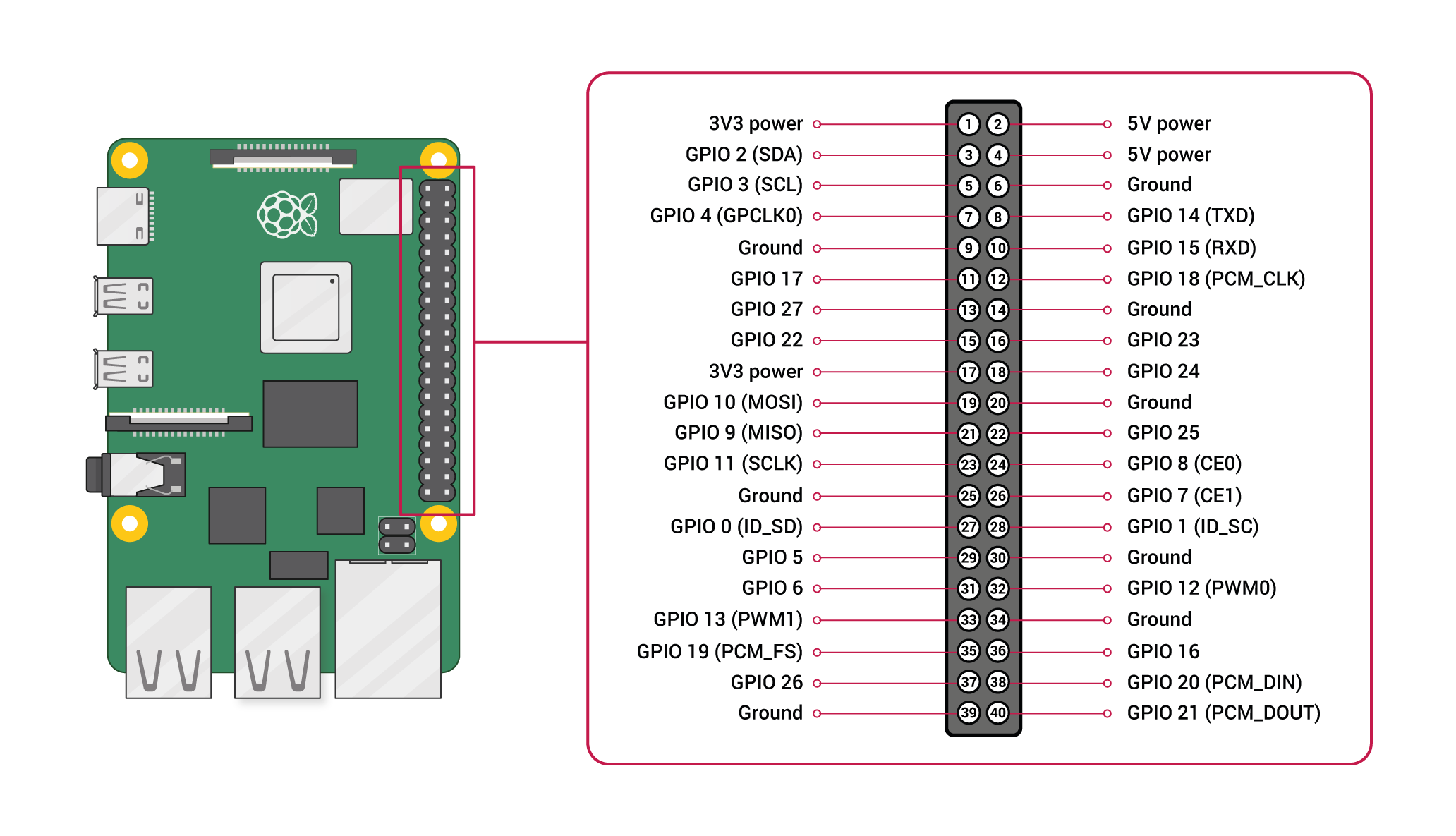
GPIO
A powerful feature of the Raspberry Pi is the row of GPIO (general-purpose input/output) pins along the top edge of the board. A 40-pin GPIO header is found on all current Raspberry Pi boards (unpopulated on Pi Zero and Pi Zero W). Prior to the Pi 1 Model B+ (2014), boards comprised a shorter 26-pin header.
Any of the GPIO pins can be designated (in software) as an input or output pin and used for a wide range of purposes.
Note: the numbering of the GPIO pins is not in numerical order; GPIO pins 0 and 1 are present on the board (physical pins 27 and 28) but are reserved for advanced use (see below).
Voltages
Two 5V pins and two 3V3 pins are present on the board, as well as a number of ground pins (0V), which are unconfigurable. The remaining pins are all general purpose 3V3 pins, meaning outputs are set to 3V3 and inputs are 3V3-tolerant.
Outputs
A GPIO pin designated as an output pin can be set to high (3V3) or low (0V).
Inputs
A GPIO pin designated as an input pin can be read as high (3V3) or low (0V). This is made easier with the use of internal pull-up or pull-down resistors. Pins GPIO2 and GPIO3 have fixed pull-up resistors, but for other pins this can be configured in software.
More
As well as simple input and output devices, the GPIO pins can be used with a variety of alternative functions, some are available on all pins, others on specific pins.
- PWM (pulse-width modulation)
- Software PWM available on all pins
- Hardware PWM available on GPIO12, GPIO13, GPIO18, GPIO19
- SPI
- SPI0: MOSI (GPIO10); MISO (GPIO9); SCLK (GPIO11); CE0 (GPIO8), CE1 (GPIO7)
- SPI1: MOSI (GPIO20); MISO (GPIO19); SCLK (GPIO21); CE0 (GPIO18); CE1 (GPIO17); CE2 (GPIO16)
- I2C
- Data: (GPIO2); Clock (GPIO3)
- EEPROM Data: (GPIO0); EEPROM Clock (GPIO1)
- Serial
- TX (GPIO14); RX (GPIO15)
GPIO pinout
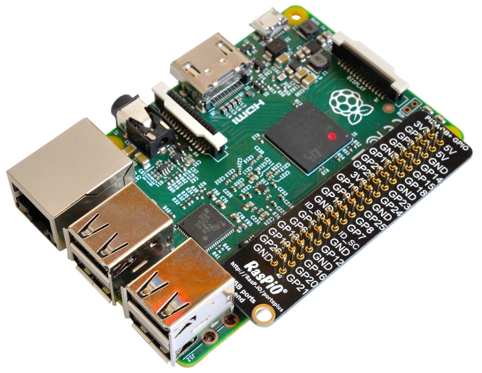
It’s important to be aware of which pin is which. Some people use pin labels (like the RasPiO Portsplus PCB, or the printable Raspberry Leaf).
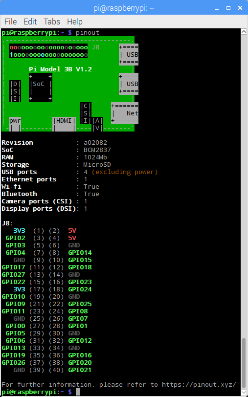
A handy reference can be accessed on the Raspberry Pi by opening a terminal window and running the command
pinout. This tool is provided by the GPIO Zero Python library, which is installed by default on the Raspberry Pi OS desktop image, but not on Raspberry Pi OS Lite.
For more details on the advanced capabilities of the GPIO pins see gadgetoid’s interactive pinout diagram.
Programming with GPIO
It is possible to control GPIO pins using a number of programming languages and tools. See the following guides to get started:
- GPIO with Scratch 1.4
- GPIO with Scratch 2
- GPIO with Python
- GPIO with C/C++ using standard kernel interface via libgpiod
- GPIO with C/C++ using 3rd party library pigpio
- GPIO with Processing3
Warning: while connecting up simple components to the GPIO pins is perfectly safe, it’s important to be careful how you wire things up. LEDs should have resistors to limit the current passing through them. Do not use 5V for 3V3 components. Do not connect motors directly to the GPIO pins, instead use an H-bridge circuit or a motor controller board.
Permissions
In order to use the GPIO ports your user must be a member of the
gpiogroup. Thepiuser is a member by default, other users need to be added manually.sudo usermod -a -G gpio <username>

Raspberry Pi GPIO Pinout
The comprehensive add-on boards & GPIO Pinout guide for the Raspberry Pi
Source: Raspberry Pi GPIO Pinout
How to Create Registry Script (.REG) Files
A: Modifying Windows Registry
Open Registry Editor, go to desired key and make changes.
B: Creating Registry Script File
Once you make changes, right-click on the registry key (which you modified) in left-side pane and select Export option.
It’ll open save dialog box to export the registry file. You just need to select the location to save the file and provide any desired name to the file. It’ll automatically create .REG file containing registry key information.
C: Editing Registry Script File
Now go to the folder containing registry script file which you created, right-click on the .REG file and select Edit option.
It’ll open the registry script file in Notepad. The format of registry script will look similar to following:
Windows Registry Editor Version 5.00
[Registry_Key_Path]
“String_or_DWORD_Name“=Value_data
The “Windows Registry Editor Version 5.00” line is essential. It defines Registry Editor version and you don’t need to edit this line. Keep it as it is. In Windows 98 and Windows NT operating systems, the Registry Editor version was defined as REGEDIT4 in registry script files.
“Registry_Key_Path” is the full path of the required registry key enclosed within square brackets ([]).
Under registry key path, name of string/DWORD/etc is written within double-quotes (“”) and after the equal (=) sign its value is written.
D: Removing Data from Registry Script File
If you want to remove any key or string/DWORD value from registry script file, you can delete its line from the file. Remember if you want to remove any particular key from the file, also remove all string/DWORD values mentioned under it.
E: Combining Multiple Registry Script Files
You can join different registry script files. Edit the files in Notepad and copy/paste one registry script contents into other registry script file. Remember the line “Windows Registry Editor Version 5.00” should always appear only once and at the beginning of the registry script file.
F: Deleting Keys and Values from Registry Editor Using Registry Script File
“Export” option of Registry Editor only allows to create registry scripts which can add/modify registry keys and values. But if you want to create a registry script which can delete an existing key or value from registry, then you’ll need to modify the registry script.
First export the registry key and value which you want to delete from registry via registry script file. Then edit the registry script file in Notepad.
Now if you want to delete a key from Registry Editor, simply add minus/hyphen (–) sign before the key path. For example, if your registry script file contains following key path:
[HKEY_CURRENT_USER\SOFTWARE\Microsoft\Windows\CurrentVersion\Policies\Explorer]
To delete “Explorer” key from Registry Editor, add minus/hyphen (–) sign before its path as shown following:
[–HKEY_CURRENT_USER\SOFTWARE\Microsoft\Windows\CurrentVersion\Policies\Explorer]
NOTE: Registry script will always delete the key from registry which is mentioned at the end of the path. In the above mentioned key path, “Explorer” key is mentioned at the end, so the line will only delete “Explorer” key from registry.
If you want to delete a value from Registry Editor, you’ll need to add minus/hyphen (–) sign after equal (=) sign following the value name in registry script file. For example, if your registry script file contains following value:
“NoDriveTypeAutoRun”=dword:000000FF
And you want to delete “NoDriveTypeAutoRun” value from Registry Editor via registry script file, then do as following:
“NoDriveTypeAutoRun”=–
When you’ll run registry script, it’ll automatically remove the mentioned key/value from Registry Editor.


Source: [Guide] How to Create Registry Script (.REG) Files in Windows – AskVG