Thanks to advances in home-based computer-aided design, CNC routers, laser cutters and 3D printers, it’s easier than ever for the home hobbyist to work in a garage workshop, from just an idea to a fully finished, professional quality pinball machine.
This wiki is not meant to be a static list of resources – anyone is welcome to edit or add information or articles on any subject relating to home brew pinball. You are only asked to sign up for an account to edit.
Click on any of the topics below to go to that specific section.
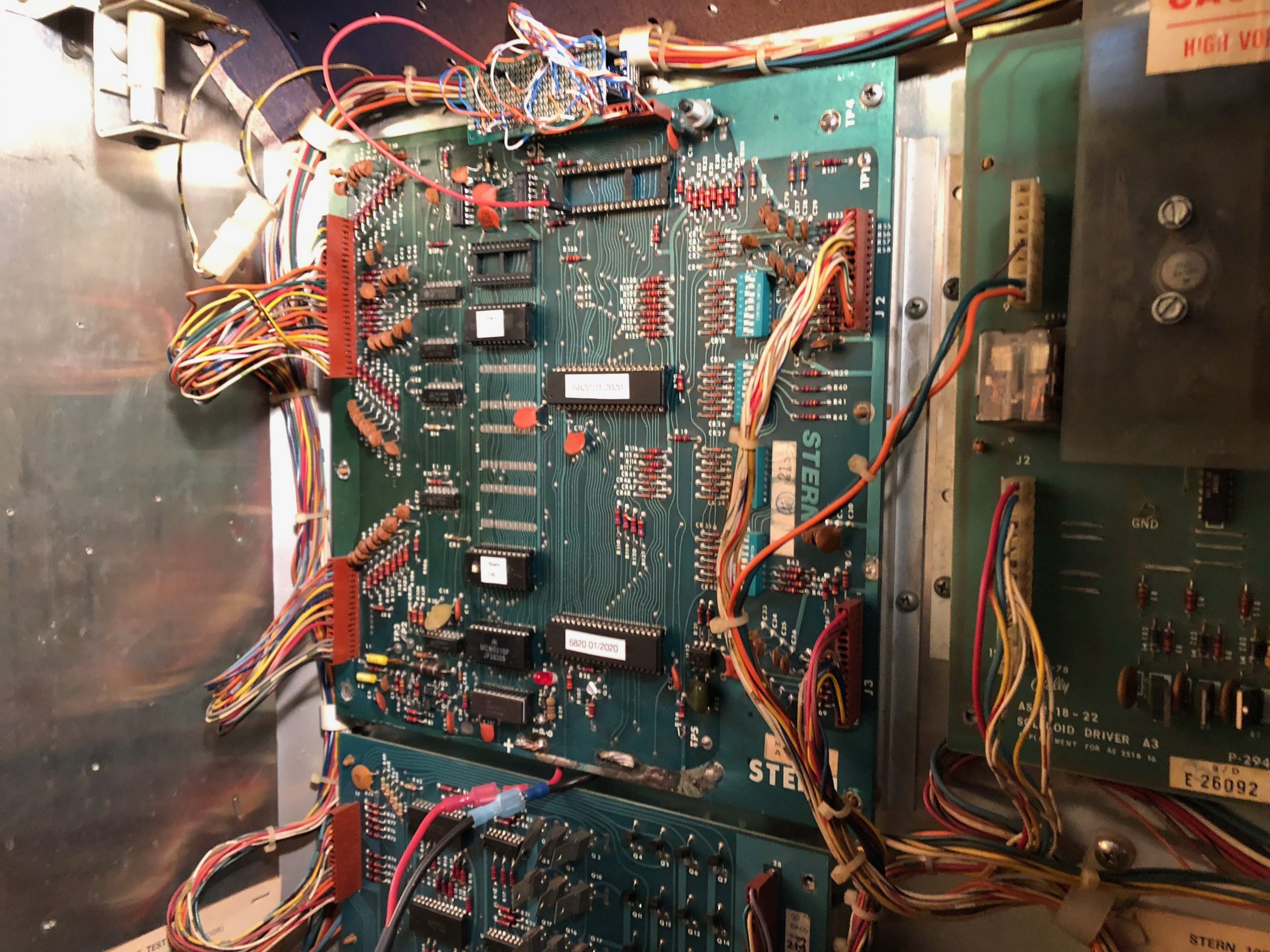
The Stern MPU-100 is identical to the Bally AS-2518-17 board. At least I think it is. I’ve worked on both, I can’t find any difference, and I’ve read that plugging the ROMs from one into the other works just fine in a game.
Here’s what I know about the architecture. The M6800 processor talks to the RAM, ROM, and PIAs with 13 address lines and 8 data lines. I don’t think A14 is used at all on this version of the board.
One little sub-circuit (using U14 and some discrete components) creates a “zero-crossing” pulse when the AC voltage crosses zero. This is fed into U10:CB1 to create a zero-crossing interrupt. Another sub-circuit creates a 320 Hz signal using U12 (a 555 timer). That’s fed into U11:CA1 to create an interrupt to update the numeric displays.
The PIA chips (U10 & U11) collect these interrupt lines and combine them to feed into U9:Pin 4 to tell the processor when things need to be done. All the interface with the real world is brokered through the Interrupt Service Routine (ISR) on the M6800. At least I’m pretty sure that’s the way it works. I’ve been through disassembled code and it appears that the timing of switch reads, lamps, and solenoid fires is all relative to the 120Hz interrupt. Displays are updated by the 320Hz interrupt. Technically, one could fire a solenoid at any time as long as it was turned off by the zero-crossing interrupt, but I don’t think that’s the way it works. I could be wrong.
So, game logic is running in a continuous loop on the M6800. It’s either in game, attract, or self-test mode at any given time, and the M6800 reads switch values from RAM (U7) to know what’s going on (the ISR is the one who puts the switch values there), and writes lamp and display updates back to RAM (U7) to be presented back to the hardware by the ISR. The M6800 stores things like credits, high scores, and audit data in U8 so it will be preserved by the batteries even when the machine is turned off.
So, for my purposes, the RAM/ROM chips (U1-U8) are unnecessary. It’s a good thing, too, because on the stock Arduino Nano, we don’t have enough pins to deal with all the address, data, and signal lines to talk to everything. Here’s how the address space breaks out:
U7 (scratchpad RAM) = 0x0000 through 0x007F
U10 (PIO) = 0x0088 through 0x008B
U11 (PIO) = 0x0090 through 0x0093
U8 (battery cRAM) = 0x0200 through 0x027F (I think?)
U2 (2k ROM) = 0x1000 through 0x17FF
U6 (2k ROM) = 0x1800 through 0x1FFF
To conserve how many pins I need on the Arduino, I only address A7, A4, A3, and A1. That allows me to point to U10 & U11. If I was really conserving pins, I could just make A7 always +5V because U10 & U11 both need it on, but I didn’t.
Capacitors are often marked with codes to show the value, tolerance and material. This is particularly true for small types such as ceramic disc or polystyrene where there is little space for full markings.
Value Codes:
The capacitance value is often marked using a 3 digit code. This works in the same way as resistor coding but using numbers instead of colours. The first 2 numbers give the value and the last number is the multiplier. These give the value in Picofarads (pF), e.g. code 103 = 1 0 000pF (=0.01uF – see Capacitance Conversion Table). Alternatively the value may be marked directly, for example 2n2 is 2.2 Nanofarads (nF).
Tolerance Code:
A single letter is often used to indicate the tolerance of the component. These can be translated using the following table:
Tolerance Code
Tolerance
C
+/- 0.25pF
D
+/- 0.5pF
F
+/- 1%
G
+/- 2%
J
+/- 5%
K
+/- 10%
M
+/- 20%
Z
– 20% +80%
Material Code:
The dielectric material is often marked in abbreviated form. The table below shows the meaning of these abbreviations.